Wing Rock
Wings with low aspect ratio, high sweep and sharp leading edges at high angles of attack undergo a self induced unsteady rolling periodic motion called ‘wing rock’. In water and wind tunnels, wings having a single degree of freedom, roll only, experiences wing rock beyond a critical angle of attack. The symmetrically formed leading edge vortices, beyond the critical angle of attack can no longer remain symmetric; therefore, their strength changes to create a moment about the axis of the wing. This moment, initially being small, causes wing to roll in one direction. Meanwhile, the vortex on the other side of the wing gets stronger and opposes the roll so that the motion reverses itself. Therefore, a self induced periodic motion is generated. In flight conditions, this rolling takes place together with the side sway and the plunging degrees of freedom. In Fig. 8.14, shown is the three degrees of freedom motion consists of (a) roll, (b) side sway, and (c) vertical displacement.
According to Fig. 8.14, the flight direction is in out of y-z plane, and the aircraft rolls about its axis while it moves sideways and descends with high angle of attack. The analysis of this three degrees of freedom motion is possible by evaluating the lifting force, sideways force, and roll moment acting on the body at every instant of the flight in interactive manner. In recent years, the three degrees of freedom problem based on the numerical solution of Euler equations to predict the aerodynamic forces and moment acting on an aircraft in wing rock appeared in literature (Saad and Liebst 2003). On the other hand, the numerical solution of Navier – Stokes equations for delta wings in free or forced rolling oscillations first appeared in the mid 1990s (Chaderjian 1994; Chaderjian and Schiff 1996).
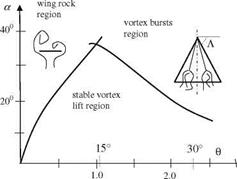
Results of years of experimental as well as numerical studies on unsteady aerodynamics are summarized in Fig. 8.15. On the left side of the graph, where all low aspect ratio wing data was presented, the wing rock occurs above a certain angle of attack for the wings having leading edge sweep more than 74° (Ericsson 1984). If the sweep angle is less than 74°, instead of formation of leading edge vortices we observe their bursting. The bursting of a leading edge vortex causes
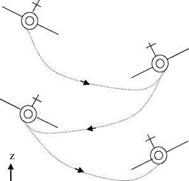 Fig. 8.14 Wing rock with three degrees of freedom: roll, side sway and plunging
> y
1.5 і і
![]()


![]()
 k=m b/U
suction loss on one side of the wing which in turn creates a dynamic instability which is called roll divergence (Ericsson 1984). Starting of roll divergence, however, spoils the periodic rocking motion and causes wing to spin about its own axis. On the right side of the graph, the large aspect ratio effects are visible in terms static and dynamic stall limits.
The numerical studies on wing rock first became possible by modeling the leading edge vortex with unsteady vortex lattice methods (Konstadinopoulos et al. 1985). In that work, the equation of roll motion was based on the conservation of roll moment with roll angle and its time rates. The roll moment equation in terms of the non dimensional moment coefficient Ct as follows
Iф = 1/2pcAU2Ct(ф, ф, a) — і/. (8-17)
Here, I is the roll moment of inertia of the wing, ф is the roll angle, A wing surface area, c root chord and і is the bearing resistance to roll. Rearranging the coefficients in Eq. 8.17, and indicating the reduced time by s = 8Ut/c the non dimensional form of Eq. 8.17 reads as
/"(s) = CiCt(/, Ф, a) —С2Ф’ (8.18)
Here, the non dimensional coefficient C = pc3S/(128I) and C2 = ic/(8I). The roll motion is started with the non zero angle ф0 and zero angular velocity. With the sweep angle of 80° and root chord of 42.9 cm the delta wing is set to roll motion at various angles of attack to result in: (a) damped rolling for the angle attack less than 15°, (b) unstable periodic roll motion for the angle of attack more than 20°.
The simple analytical model construction of roll moment helps to analyze the wing rock phenomenon. Now, we can write a general expression for the non dimensional roll moment coefficient in terms of roll angle ф and the time rate of change of that angle ф0 as follows
C — & ф b a2ф b аз ф – Ь a4 ф ф – Ь a 5 ф ф – Ь a6 ф b a7 ф – Ь a 8 ф ф b a9 ф ф
![]() Here, non dimensional coefficients a are computed by least square method. The first six terms on the right hand side of the Eq. 8.19 contribute significantly to the value C1, and the rest of the terms are insignificant. In addition, the terms with odd powers of ф constitute the restoring force, and the odd powers of ф are responsible for damping of the roll motion. Accordingly, we can write down the force coefficient CR which is responsible for the restoring force, the coefficient CD which is for the damping as follows
Here, non dimensional coefficients a are computed by least square method. The first six terms on the right hand side of the Eq. 8.19 contribute significantly to the value C1, and the rest of the terms are insignificant. In addition, the terms with odd powers of ф constitute the restoring force, and the odd powers of ф are responsible for damping of the roll motion. Accordingly, we can write down the force coefficient CR which is responsible for the restoring force, the coefficient CD which is for the damping as follows
Cr — а ф b a3ф ~b a5ф ф (8.20a)
and,
Cd — a2ф b a4ф ф b a6ф • (8.20b)
Example 3 At 250 angle of attack, a wing with 80° angle of sweep rocks with period of 0.39 s. and amplitude of 32°. Obtain the graph of Cr versus ф and Cd versus ф, and comment on them.
Data: a1 = -0.0572, a2 = 0.1362, a3 = 0.0514, a4 = -1.403, a5 = -1.943, a6 = 0.075.
Solution:
1. The data is used to express the roll angle in radians ф = -32 sin (2pt/0.39)p/ 180 and writing non dimensional ф, the restoring force coefficient reads as
Cr — —0.0572ф + 0.0514ф3 – 1.943<ф2ф
whose graph is shown Fig. 8.16 which gives the force coefficient in opposite phase with roll angle. These two being in opposite phase make the motion
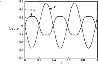 Fig. 8.16 Change in restor ing force for the wing rock 10Cr and ф by time
continue in a stable manner. The roll angle changes sinusoidally, however, because expression Eq. 8.20a being non linear, CR is periodic but no longer simple harmonic, as seen in Fig. 8.16, especially at the flat peaks of CR curve.
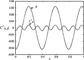
2. The aerodynamic damping coefficient is obtained by subtracting the bearing resistance from Eq. 8.20b as CD = 0.1362 / — 1.403/2/ + 0.075/3 — 0.004/. Shown in Eq. 8.18 is the aerodynamic damping coefficient CD and roll rate / with time. According to Fig. 8.17 the period of damping coefficient is the half of the period of roll rate. (The equations are used with permission of the ‘‘American Institute of Aeronautics and Astronautics’’).
According to Figs. 8.16 and 8.17, when the roll angle is approximately zero and the roll rate is near maximum, the damping moment and the roll rate have the same sign, and when the roll angle is maximum and the roll rate is zero, the damping moment and the roll rate have opposite signs. For this reason when the roll rate is maximum, since it has the same sign with the damping moment, there is a loss in damping which means there is a positive feeding of the motion. That is how the wing rock is sustained.
Example 4 Plot the hysteresis curve for the roll moments roll angle for the delta wing given in Example 3. Indicate the intervals on the hysteresis curve where the motion is damped and where it is fed. Compare the new plot with the comment made on the previous graph.
Solution: The total rolling moment coefficient is
CT = CR + CD
 |
whose graph with respect to roll angle / is plotted in Fig. 8.18. In that figure when the curve follows the clockwise pattern, there is a negative damping, and the counterclockwise pattern there is a damping. Accordingly, as far as the intervals are concerned, in -32 < / <-18 and 18 < / < 32 there is
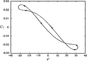 |
damping and in -18 < ф < 18 feeding occurs. A similar conclusion is made at high roll angle where there is a negative damping observed.
Examples 3 and 4 provided us with detailed information about the rolling moment change with roll angle of a wing in a wing rock as a single degree of freedom problem. During the rolling motion of a wing, except at zero yaw angle, while the effective angle of attack changes, the free stream direction also changes with an amount b as the yaw angle as indicated with 3-D representation on Fig. 8.19.
Now, let us express the effective angle of attack ae, and the effective yaw angle be in terms of roll angle ф = Аф sin xt. Here, Аф is the amplitude of roll angle.
|
ae = arctan(tana0 cos/) |
(8.21) |
|
be = arctan(tana0 sin/). |
(8.22) |

For ф = 0 yaw angle we take the angle of attack as a0. During the rolling motion we consider only the rotational degree of freedom around the root chord of the delta wing. However, Eqs. 8.21 and 8.22 indicate that as the effective angle of attack deceases, the emerging sideways flow causes the flow symmetry to be spoiled. For this reason, the normal force acting on the delta wing changes during rolling and also because of spoiling of symmetry. Shown in Fig. 8.20 is the
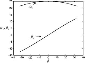 |
variation of the effective angle of attack and the yaw angle with the change of roll angle as given in Examples 3 and 4 for a0 = 250 and Аф = 32°. Accordingly, the effective yaw angle changes between -12.5° and 12.5°, while effective angle of attack varies between 22° and 25°. Since the effective angle of attack decreases with rolling, the normal force also decreases. In experiments, however, the static and dynamic cases change in the normal force is found to be different (Levin and Katz 1984). The measurements of Levin and Katz indicate that the time average of the normal force coefficient measured during the roll is smaller than the statically measured values. This difference, for the angles of attack less than 32°, is due to unspoiled vortex symmetry at zero roll angle of for static case, and continuously existing asymmetry for the dynamic case. At higher angles of attack, the vortex bursts occurs earlier for the dynamic case than it happens for the static case which makes the average normal force coefficient for the dynamic case to be 15-20% less than that of the static case.
The measurements made on the delta wing given in Example 3 suggest that during rocking, the oscillatory aerodynamic side force acting on the wing has amplitude of 0.5 and a small phase difference between the roll angle (Levin and Katz 1984). About the rolling characteristics of the delta wing of Example 3, there is detailed information related to experimental results, conditions and comments at 20°, 25°, 30° and 35° angles of attack given in Levin and Katz. On the other hand, the frequency of the normal force coefficient is double the frequency of rolling, and the amplitude changes are in minimum 0.3 and maximum 0.7. In their work, the dynamic values of normal and the sideways forces in terms of static and the roll angle values /max and /av ffi /max/2, as upper and lower limits read,
cndy CNsTC°s/av (8.23a)
CYmaks ^ CNSTsin/maks* (8-23b)
During wing rock the maximum dynamic normal force coefficients, as stated before, can not exceed the values attained in static cases as given by inequality
Eq. 8.23a. On the other hand, according to Eq. 8.23b, the lower limit of the side force acting on the wing is proportional with the static value of the normal force. This means, even for a single degree of freedom problem, there is a minimum sidewise force created. For this reason, in real flight condition wing rock analysis we need to consider the sideways and vertical degrees of freedom in addition to the rolling as shown in Fig. 8.14.
Three degrees of freedom simulations in wind tunnels require building of mobile models which are quite expensive to operate, when possible. This forces us to make measurements in flight conditions and/or to perform detailed numerical simulations to compare the results obtained with single degree of freedom problem (Saad and Liebst 2003). In their work, Saad and Liebst use numerical solution of Euler equations to compute the flight path under the aerodynamic forces computed as three degrees of freedom problem. The kinetic yaw angle can be computed if we take the v as the velocity normal to free stream as follows
Ann = arcsin(v/U). (8.24)
The total yaw angle is determined with addition of angles given by Eqs. 8.22 and 8.24 and. The geometry of the wing consists of a cone with 30° cone angle and a delta planform with 60° sweep. Two different flow case studies were done about this geometry: first study involves only the roll degree of freedom, and the second study was done with three degrees of freedom. The following was observed:
1. The angle at which rocking starts is 5° higher for three degrees of freedom.
2. Roll angle amplitude is 50% for the three degrees of freedom.
3. The sideways motion has 90° phase difference with rolling, which contributes to damping.
4. The occurrence of vortex burst causes the amplitude for three degrees of freedom to be less.
5. The vortex dynamics suggests that the pitching degree of freedom should be included in wing rock analysis.
The comments made above are only based on the numerical solution of Saad and Liebst, and they are not validated by flight measurements.
On the other hand, based on the Navier-Stokes solution, one degree of freedom problem was studied in detail with comparing experimental data given for rolling by Chaderjian and Schiff. Their study is made for the 65° swept delta wing mounted on 8% thick cone-cylinder body. In their study, they consider 15° angle of attack, Reynolds number of 3.67 x 10⁶, Mach number of 0.27, and maximum roll angle of / = 40°. The dynamic roll motion occurs at a frequency of 7 Hz, and the normal force coefficient shows similar behavior to that of experiments while it is predicted little less than the static force coefficient. Another important conclusion made in their work is the moving of center of pressure towards trailing edge for the dynamic case as compared to the static case. Here, low values of the normal force coefficient could be the reason for the center of pressure to move towards the trailing edge. In addition, the roll moment versus roll angle hysteresis curve is in counter clockwise direction, similar to the case of experimental measures, which indicates that the motion has a damping character. The delta wing left free to roll from the maximum roll angle shows a damping motion experimentally, whereas Navier-Stoke solutions predicts over damping. These computations and experiments are performed at 30° angle of attack, and they converge not to zero roll angles but to half of the maximum roll angle! This shows that if the roll motion is not forced then the delta wing can undergo unsymmetrical damping motion.
The wing rock motion or rolling studied so far is for the slender delta wing whose vortex dynamics is well understood. The non slender wings with round leading edges having about 45° sweep angle at high angles of attack may undergo wing rock for different aerodynamic reasons (Ericsson 2001). The effective angle of attack, as shown in Fig. 8.19b, because of effective yaw angle reads as
Aeff = Л ± arctan(tanrsin/). (8.25)
Here, r is the angle between the roll axis and the free stream direction. The effective sweep angle increases on one side of the wing while it decreases on the other side to spoil the symmetry of the vortices. This causes a net roll moment also on the non slender wings, which may lead to the wing rock. Once the wing rock started, one side of the wing goes up and the other side goes down relative to the root chord. The flow separation becomes possible when the effective angle of attack, Eq. 8.21, is near stall angle. For rolling motion to be continuous and periodic wing rock the negative dissipation is necessary. The necessary negative damping is provided by the ‘moving wall effect’ acting on the boundary layer near the stagnation region. At high angle of attack near the flow separation, the moving wall effect makes the flow to reattach at the uplifting side of the wing and increases the lift at that side while the wing rocks. This way the force increases with the increasing direction of motion to create negative damping. On the other side of the wing which is moving downwards, the moving wall effect increases the separation, which in turn decreases the lift on that side, and naturally reduction in the force and the motion in the same direction create reduction in the damping. Thus, occurrence of negative damping on both sides creates enough energy for wing to rock. This is how the flow induces rocking motion on the non slender wing with round leading edge (Ericsson 2001).
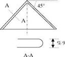
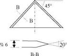
For two different non slender wings both with 45° sweep angle as shown in Fig. 8.21a, b, one with the round the other with the sharp leading edges and lower thickness, we observe a completely different rolling behavior at high angles of attack (Ericsson 2003). The planform given in Fig. 8.21a is a 9% thick delta wing with round leading edge and the other planform is 6% thick with sharp leading edge.
For both types of wings given in Fig. 8.21, the experiments performed at high angles of attack give 50% less rolling moments compared to slender delta wings. The sharp leading edged wing at 20°-25° angles of attack is damped at roll angles of 42° and 0°, respectively when it was left free at 28° roll angle. On the other hand, for the round leading edged wing at 30°-35° angle of attack range, we observe damped motion at zero roll angle which is left to roll at angles /
![]()
 |
 |
 |
(b)
= 10° and 30°, respectively. At 25° and 30° angle of attack, the round leading edged wing when left free to roll from 30° roll angle, rocks with 20° roll amplitude at about / = 50°. This means that the undamped rolling motion can be observed experimentally only for the non slender wing with the round leading edge starting from certain roll angles. The observed rocking motion is quasi periodic with an approximate period of 1.5 s. This shows that non slender delta wings with moderate sweep have rocking frequency of one order of magnitude less than that of the slender wings with high sweep. This finally proves that the aerodynamic effects causing the rocking of non slender wings occur slower than that of slender wings.
There is a third kind of wing rock occurring at high angles of attack caused by the periodic shedding of the vortices around the left and right side of a fuselage (Ericsson et al. 1996). For an aircraft having slender fuselage with moderately swept wings at high angles of attack, i. e. a > 30° which exceeds static stall angle, we observe this type of wing rock induced by the shedding of vortices from the part of the fuselage which is ahead of the wing. The occurrence of this kind of rocking motion is caused by the vortex shedding from the separated cross flow about the frontal portion of the fuselage. A cylindrically shaped front body rolls about its axis with an angular velocity while it rocks. During this rolling, there is also a vertical flow because of high angle of attack flow separation. Depending on the value of the Reynolds number based on the cross flow velocity there exists a Magnus force, with known magnitude and direction, acting on the cylinder (Ericsson 1988). The Magnus effect on the cylinder is in the positive direction because of the speed of rotation causing the flow is subcritical and laminar. With the increase in the Reynolds number if the critical flow condition is reached, there emerges a Magnus force which is in opposite direction. In flight conditions the wing rock caused by frontal body is observed experimentally at this critical flow regime. When the Reynolds number based on the free stream speed, body diameter and kinematic viscosity is in the range of 1.0 x x 105, the critical
flow conditions are reached. In Fig. 8.22a, b shown is the negative Magnus effect acting on the rotating cylinder in critical flow conditions. The rotational effect on the cylindrical surface causes early transition at the right side of the cylinder, and at the left side the transition is late. The early transition at the right side of the cylinder and reattachment causes a suction force creating negative Magnus force. Meanwhile, from the right side a counter clockwise rotating vortex is shed to the
(b)
![]()
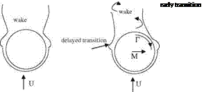 |
wake. This newly shed strong vortex creates a rolling effect which slows down and stops the clockwise rotation, and causes cylinder to rotate in counter clockwise direction. This time at the left side of the cylinder we observe a suction creating a Magnus force directed towards left. That is how the self induced motion feeds itself in creating sustainable wing rock action. In practice, the wing rock caused by the frontal body is the slowest rocking motion with the period of 3.5 s. Here, the flow separation from the moving body and the vortex shedding play an important role in determining the period of wing rock.
Assuming that an axisymmetric frontal body without a tail wing rocks similar to that shown in Fig. 8.22, we can construct the theoretical hysteresis curve for the roll moment versus roll angle as shown in Fig. 8.23a. The ideal curve given in Fig. 8.23a has the negative damping property for the rolling motion; therefore, the wing rock is self sustainable. The ideal curve indicates that as the body rotates in clockwise direction, the roll angle increases to its maximum value, and when the angular speed is 0, the roll angle reaches its maximum value and changes its direction to counter clockwise rotation. Let us denote the time between two successive vortex shedding as At. Then the counter clockwise rotating body with the increase of negative roll moment goes back to the zero roll position so that in At time interval it starts from 0 roll angle and goes back to 0 roll angle position. In the next At time duration it completes its roll to the left side. Finally, in 2 At time period it completes one cycle of its motion.
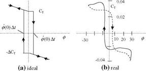 |
In Fig. 8.23b we observe the real version of the wing rock due to vortex shedding from a frontal portion of a fuselage which rocks in -30° and +30° roll
angles. The clockwise direction of the curve near the zero roll region indicates the negative damping while in extreme angles the counter clockwise direction is indicative of positive damping. The difference between the two supplies the necessary energy for rocking.


