CFD Modeling of the Rotor Wake
While the flows about the rotor blades themselves have received the most attention, and CFD methods have certainly provided considerable physical insight into the roll-up of the tip vortex and initial formation of the rotor wake, adequate modeling of the subsequent dynamics of the rotor wake has proved a more daunting task. Yet it is the proper modeling of the geometry of the rotor wake that is probably the most important step in the calculation of the entire helicopter flow field. Although there has been some progress in Navier-Stokes based CFD modeling of the rotor wake and the flow field around the entire helicopter, the inability of most current CFD methods to protect this vorticity from the effects of numerical diffusion continues to yield an active area for research. ^Furthermore, the large number of grid points required to define the flow domain for a helicopter rotor continues to challenge even the most powerful computers, with memory demands that are quite formidable even by current-day standards.
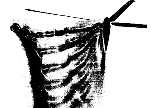
One significant problem with wake modeling is that the numerical error in any approximation to the Euler or Navier stokes equations tends to introduce artificial diffusion of vorticity, which smears vorticity in the flow more quickly than is observed from experiments. An example is shown in Fig. 14.12, and while capturing the key features of the wake
|
Figure 14.12 Navier-Stokes solution of a helicopter rotor wake in hovering flight. 64 million grid points are used. Contours of vorticity magnitude are computed on a cutting plane located at 45° behind one of the rotor blades. Source: Strawn & Djomehri (2002). Image courtesy of US Army AFDD and Roger Strawn. |
structure, the coherence of the tip vortex itself is quickly lost to numerical diffusion. This occurs well within a rotor revolution. Based on flow visualization, tip vortices may persist clearly to four or more revolutions. Vortex methods (described in detail in Section 10.7) give a good level of approximation to the problem of defining the strength and vorticity of the rotor wake and have a strong advantage in being able to preserve vorticity independently of grid resolution or vortex age (see Section 10.7.3). Some progress has been made using hybrid schemes where a CFD-based solution for the blade aerodynamics is coupled to one of the vortex wake models discussed in Section 10.7. The inflow (induced velocity field) from the vortex wake model forms a boundary condition to the computational domain of the CFD model, arid data are passed back and forth between the two calculations until convergence is obtained. Full-potential methods have also been used for this purpose, and with sufficient engineering judgment have produced remarkable agreement with experimental measurements of the blade pressure distributions, including the critical area near the blade tip. See Caradonna (1990) for a good review of prior work in this area.


