Effects of viscosity
Flows at hypersonic Mach numbers can bring about drastic changes in the effects which viscosity can have, especially when the air can no longer be treated as a perfect gas and the so-called real-gas effects must be taken into account. But we have already seen that the waverider aircraft we have in mind are not likely to penetrate deeply into flight regimes where the speeds and temperatures are so high that real-gas effects
dominate the flow. Therefore, we are primarily interested in flows where effects of viscosity can still be assumed to be confined to boundary layers in perfect gases. But, in such boundary layers, there are now significant gradients normal to the surface not only of the velocity but also of the temperature, T, and the density, p. The basic theory of such boundary layers is well-developed, and we refer here to textbooks by H Schlichting
(1960) , A Walz (1969), and R N Cox & L F Crabtree (1965) and to an extensive survey by R Michel (1968), where further references may be found.
Apart from the introduction of two further variables, T and p , we must also include the possibility that the viscosity, у, the thermal conductivity, к, and the specific heat of air, cp, are all functions of the absolute temperature. Thus we have to consider a further non-dimensional parameter to characterise heat transfer, in addition to the Reynolds number and the Mach number. A suitable parameter is the ratio between the rates of diffusion of vorticity and of heat, which is called the Prandtl number and defined as
The numerical value of the Prandtl number for air at room temperature is about 0.7, which is not far from a value unity that leads to some simplifications.
In fact for twodimensional steady laminar flow with Pr = 1 , the boundary – layer equations give the same function of z for both the velocity profile Vx(z)/Vq and the temperature profile T(z)/Tq, so that the thicknesses of the velocity and thermal boundary layers are then identical. This is the so – called Reynolds analogy, which postulates that heat and momentum are transferred by the same mechanism, and which is often assumed to hold also in turbulent flows and when the Prandtl number is not unity. If we measure the heat, qw, transferred across unit area to or from a wall at the temperature Tw from or to a stream at the temperature To by the non-dimensional Stanton number
the Reynolds analogy states that
![]() St = JCf T
St = JCf T
w
where C, = ■ –s-
К
is the skin-friction coefficient. These simple relations indicate at least that it is worthwhile to investigate heat transfer and skin friction together. Considerations of similitude also play an important part in hypersonic aerodynamics (see e. g. L Lees (1953), W D Hayes & R F Probstein (1959), J Zierep (1971)). Some phenomena depend not only on Mach number and Reynolds number separately but only on a combination of the two. For example, hypersonic flowfields may depend primarily on a parameter proportional to Mg/i^Re. Another significant parameter is
which can be shown to be proportional to the boundary-layer thickness. These considerations indicate that viscous interactions between the boundary layer and the external flow become more and more important as the Mach number increases.
In this section, we shall discuss some effects of viscosity, which have a bearing on the design of waverider aircraft with aerodynamically sharp leading edges:
skin friction, aerodynamic heating, and displacement effects in attached boundary layers;
conditions which may lead to flow separations, and possibly reattachment, and the consequences of such flow phenomena;
a brief digression into some problems of re-entry vehicles, in as much as they may reveal and clarify effects in a strong manner, which may occur weakly also on waverider aircraft;
flows with injection of a different gas and boundary layers with injection or suction;
effects of heat conduction in the body, especially near the sharp leading edges of waveriders.
This selection of topics evidently covers only a small portion of the field of conventional hypersonics, which is dominated by blunt-body aerodynamics. Thus we shall not discuss a kind of interaction, which is typical of blunt – body flows, and which is caused by the vorticity generated in the stream outside the boundary layer by a highly-curved bow shock. This vorticity may have a strong influence when it is of the same order as the average vorticity in the boundary layer associated with the shear stress. We assume here that such conditions may largely be avoided in the design of waverider aircraft. But strong viscous interactions may also occur on wings with sharp leading edges, especially at the moderate Reynolds numbers frequently encountered in test facilities. We refer here to the work of J C Cooke (1964) and L Davies
(1970) on how possible changes in the viscous-induced force and moment characteristics may be estimated. Note that the full-scale Reynolds number is likely to decrease with Mach number, mainly because the flight altitude is expected to increase (from around 25km at Mq = 5 to around 35km at M0 = 10).
We have already mentioned some of the many methods for calculating the development of compressible boundary layers in earlier chapters. For laminar layers, we refer especially to the methods by С C L Sells (1966), С В Cohen & E Reshotko (1955), and N A Jaffe & A M 0 Smith (1972). Such methods can, in principle, be extended to apply to regions of strong interaction between the boundary layer and the external stream, by simultaneous solution of the boundary-layer equations together with a relation between pressure and flow direction at the edge of the boundary layer obtained from the isentropic flow equations. L Lees & В L Reeves (1964) have derived one such method based on the boundary-layer integral equations for momentum and moment of momentum, and have used it to give successful predictions of shock-induced separation and reattachment. Subsequently, J M Klineberg & L Lees (1969) extended the method to apply to flows with heat transfer. When the boundary-layer equations are coupled in this way with a relation between pressure and flow direction at the edge of the boundery layer, a singularity arises that was discussed in both these papers. In consequence it was found necessary to distinguish between subcritical and supercritical viscous flows in their methods. J L Stollery & W L Hankey (1970) have shown that, by using a simpler boundary-layer method, the critical boundary that arises from the equations can be removed from the domain of practical interest, and is therefore, they argue, of no physical significance. A W Bloy HP Georgeff
(1974) have found that the method of Klineberg & Lees gives good agreement with their measurements of surface pressures and heat transfer rates in twodimensional flows over sharp compression and expansion corners at Mg = 12 , and В G Gautier & J J Ginoux (1973) have modified it to compute viscous interactions over a continuous range of ratios between wall and stagnation temperatures. They found satisfactory agreement with experimental results for twodimensional flows over flat plate-wedge models with widely-different wall cooling rates, and their method may be regarded as a significant improvement over previous attempts to calculate viscous interactions where the wall temperature distribution is prescribed. E H Hirschel (1975) had discussed various methods concerned with boundary layers or boundary-layer-like flow – fields at high Mach numbers, which are dominated by viscosity rather than displacement effects, and where strong pressure gradients normal to the surface may occur. He has derived the general equations governing such flows and recommends the application of finite-difference rather than integral methods for their solution.
For turbulent boundary layers, we refer to calculation methods by J C Rotta
(1959) , L F Crabtree et at. (1965), J E Green (1972), D В Spalding & S W Chi (1968), H Fernholz (1969) and (1971), К G Winter & L Gaudet (1970), P Bradshaw & D H Ferriss (1971), and J E Green et at. (1972). It cannot yet be said that the relative accuracy of these methods has been assessed, even for twodimensional flows at fairly low Mach numbers. Some theoretical as well as experimental uncertainties remain unresolved, as has been demonstrated, for example, in carefully-executed yet incomplete experiments on a flat plate by D G Mabey et at. (1974). They found that the measured velocity profiles can be fitted very closely to the family of theoretical profiles proposed by Rotta; and that the technique developed by J M Allen (1968) for estimating skin friction is fairly accurate. The flat-plate skin-friction laws of Spalding & Chi and of Winter & Gaudet are in fairly good agreement with the measurements but significant deviations become apparent when the Mach number is increased (to the still relatively low value of 4.5). The measurement of temperature profiles still presents some difficulties, but there are now well-established techniques for measuring heat transfer to the wall (see e. g.
D L Schultz & T V Jones (1973) and К G Winter et at. (1975)). Available techniques for measuring the total temperature profile through the boundary layer have been examined by G Drougge & G Hovstadius (1975) and their accuracy assessed. Measurements by existing probes of different designs have been made, both simultaneous measurements in a given facility and comparative measurements with the same probe in different facilities. In general, the agreement between the various probes is good, but some unexplained anomalies remain.
For caret wings, the overall skin-friation drag Сцр does not vary much with Mach number if it is measured as a fraction of the total drag Cj)m reached when L/D has maximum value which, in turn, is generally close to. the L/D – value at the design condition. For relatively thin •wings (t « 0.04), the skin friction share is about 1/3 of Срщ and thus about the same as that for slender wings at supersonic speeds. But it is only about 1/5 for thicker lifting bodies (t «0.1) which have a higher pressure drag. Thus skin
friction matters relatively less on thick lifting bodies than on any other type of aircraft, and the emphasis is shifted towards the problems arising in connection with aerodynamic heating and with the achievement of natural laminar flow.
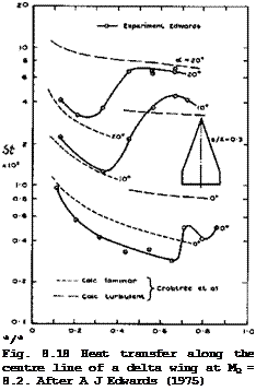
Uncertainties in estimating skin friction and heat transfer become considerably greater when the flow is threedimensional. We must then rely mainly on experimental data, and there are not many of these. Tests on delta wings are relevant in the present context, and we refer to those by H Thomann (1962) and A L Nagel et al. (1966). Some typical results of heat-transfer measurements by A J Edwards (1975) on the compression side of a flat-cropped, delta wing are reproduced in Fig. 8.18 (for Re = 1.4 * 10^, Mq = 8.2) . The heat
 LIVE GRAPH
Click here to view transfer along the centre line of the model is given in form of Stanton numbers. The outstanding feature of the results is the large variation of St along the chord, especially at the higher angles of incidence. This may be attributed to transition from the laminar to the turbulent state, which typically takes a considerable length to be completed. This can clearly be seen by comparison with the curves calculated according to L F Crabtree et al• (1965). Transition is probably caused by the sweeps or crossflow, instability described by W E Gray (1952, unpublished) and P R Owen & D G Randall (1952).
G T Chapman (1961) has shown that their criterion remains valid also in supersonic flows. At a ■ 0 , the boundary layer appears to be laminar over about 2/3 of the length. Transition moves gradually forward as the angle of incidence is increased. Very roughly, the ‘transition line’ is parallel to the leading edge at some constant distance downstream of it.
Thus the state of the boundary layer is of considerable importance not only for lift and drag, as we have already seen in connection with Fig. 8.4, but also for heat transfer. Unfortunately, the transition process is still imperfectly understood and transition Reynolds numbers are difficult to measure and to calculate, as they depend on many factors. Here, we can refer only to a few of the many papers on the subject, such as those by В E Richards & J L Stollery (1966), J L Wilson et at. (1969), and to the very extensive review by M V Morkovin (1968). Generally, in the range of Mach numbers of interest here, transition Reynolds numbers between about 106 and 10^ have been measured, but higher values up to about 3 x 10? have also been found. It appears that the transition Reynolds number, based on conditions at the edge of the boundary layer and on the distance from the leading edge to the midpoint of the transition zone, increases as the flight Mach number increases. Heat loss from the surface by radiation or conduction has the effect – within certain limits – of increasing the transition Reynolds number still further: typically, the combined effects of Mach number and heat loss may increase the transition Reynolds number by an order of magnitude between subsonic speeds and a Mach number of about 10. Yet another effect of the Mach number on the laminar boundary layer is to decrease its sensitivity to roughness (see e. g.
J L Potter & J D Whitfield (1962)). Again, typically, the size of roughness to have a significant effect on the transition Reynolds number on a flat plate may increase by an order of magnitude between subsonic speeds and a Mach number of about 5. For these reasons, hypersonic flight speeds offer the prospect of higher transition Reynolds numbers than those obtained at lower speeds, without special attention to surface finish. It may be possible to achieve natural laminar flow over large parts of the surface, without all the accessories which usually detract from the potential advantages of this type of flow. J R Collingboume & D H Peckham (1966) have considered these matters in some detail and conclude that even all-laminar boundary layers on both surfaces of a caret-like aircraft may be a feasible prospect for a relatively small aircraft (of a weight of about 200kN) with a low wing loading at cruise (of about 1.2kN/m^) at a Mach number of about. 10; the associated surface temperatures may be about 600°C or less.
In this context, the flow near the leading edges needs special consideration. The pressure field may be such that the flow within the boundary layer is directed inwards whereas the streamlines at the edge of the boundary layer may be deflected outwards. These crossflow conditions produce longitudinal vorticity which contributes to instability and reduces the transition Reynolds number. Now, the leading edges of the waverider aircraft discussed here are intended to be nominally sharp, but will have a certain finite radius in practice. Collingboume & Peckham have estimated values of the critical nose radius below which heat-transfer rates should correspond to theoretical values for a laminar boundary layer, and above which the heating rates exceed these and hence, it is inferred, transition to turbulent flow has begun at the attachment line along the leading edge. For a caret-wing aircraft with s/Я = 0.3 and a wing loading of 1.2kN/m*, they estimate the critical nose radius to be about 1.5cm at Mg = 5 , and about 2.5cm at Mg = 10 . It may be feasible to achieve these small values in practice. The structural implications of this will be discussed further below.
The actual temperature at the attachment line along a swept cylindrical leading edge may be estimated, for example, by a method developed by I E Beckwith & J E Gallagher (1961). The results have been found to be in good agreement with experimental results obtained by A Naysmith (1971) in free-flight tests on a caret wing with rounded leading edges.
Returning to the compression surface of wings, we note from the results in Fig. 8.18 that even a simple strip theory, based on calculations for twodimensional flows by L F Crabtree et at. (1965) can represent at least the general trends fairly well, if the state of the boundary layer is known. The method of D В Spalding & S W Chi (1968), applied in this way, gives similar results. But A J Edwards observed significant threedimensional effects away from the centre line, which cannot readily be predicted. Strip theory, based on local distances from the leading edge, has also been applied to experimental results on caret wings with some success by J Picken & G H Greenwood (1965), R A East & D J G Scott (1967), and G H Greenwood (1971) and (1974). Greenwood tested a caret wing with a right-angle comer at the ridge line at speeds up to Mg = 4 and found that the heat-transfer rates in the immediate vicinity of the comer are reduced to about 60% to 70% of the level away from the corner, where the measured heating rates are in good agreement with estimates from a strip theory, based on results for the twodimensional turbulent flow over a flat plate. This strong and favourable comer effect may be associated with the near-conical nature of the flow, which was probably conically subsonic under the test conditions. The opposite effect has been found by H Pfeiffer & H J Schepers (1974) in tests near a streamwise right-angle corner between two flat plates with sharp unswept leading edges. There, streamwise vorticity and an associated secondary shockwave near the comer increase both skin friction and heat transfer substantially. These effects may be of considerable practical importance and require much further elucidation. But we may conclude in general terms which kind of corner should be avoided in aircraft design and which may be used in engineering applications.
We can now consider the boundary-layer characteristics of caret wings in some more detail to get at least a notion of what the main effects may be.
J R Collingbourne & D H Peckham (1966) have investigated the broad effects of the shape, wing loading, flight altitude, and transition Reynolds number on skin friction and on the aerodynamic efficiency of caret wings. Calculations for both laminar and fully-turbulent boundary layers have been carried out by D Catherall (1962) and (1964), who determined the displacement thickness, the shear stress, and the temperature at the wall for a number of design cases.
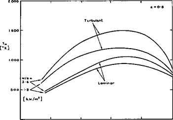
In general, in the Mach number range of interest here, the displacement thickness can be expected to be small compared with the dimensions of the body, and the interference effects between the two sides of the compression surface may not be large and may possibly be favourable. C S Sinnott (1963) has carried out extensive calculations of the temperature at the wall for turbulent boundary layers under conditions of equilibrium between convective heat transfer to the wall and heat radiation away from it. The emissivity factor has been taken as є – 0.8 in the examples quoted below. It emerges that the surface temperature on the compression surface depends mainly on the wing loading (see equation (8.10)) and not so much on the altitude of flight, above an altitude of about 30km. It is, therefore, possible to obtain a rough guide to the surface temperature to be expected by plotting this nearly – constant value against the flight Mach number for various values of the wing loading.
An example is shown in Fig. 8.19 for the temperature at a station which lies about 10m downstream of the leading edge. Upstream of this station, the temperatures are higher and downstream they are lower. We find that the temperatures increase substantially with Mach number. That they fall again at higher Mach numbers is caused by the fact that account has been taken of the centrifugal forces acting on the mass of the aeroplane, which allow a reduction in the lift to be obtained from the compression surface. But this
LIVE GRAPH
Click here to view
 |
О З Ю lb 20 25
Me
Fig. 8.19 Equilibrium wall temperatures. After Sinnott and Catherall
occurs beyond the range of Mach numbers we have in mind for waverider aircraft. We note that the temperatures are generally not high enough to bring in real-gas effects in a major way; they may matter only in localised regions. We note especially the large differences between the temperatures in turbulent and in laminar boundary layers. In view of the considerable heating problem which these aircraft are bound to have, it is vitally important to know not only the development of the boundary layer to a high degree of accuracy but also where у and in what way> transition occurs. For example, if the boundary layer remained turbulent, then the surface temperature would increase considerably if the flight Mach number were increased from 5 to 10. If, on the other hand, the boundary layer was turbulent at Mq – 5 but fully laminar at Mo = 10 , then the surface temperature would remain roughly constant throughout this Mach number range.
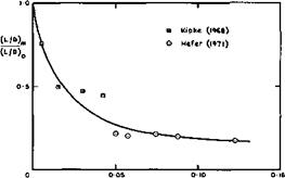
Some instructive experimental results for flows where the effects of viscosity Were especially large have been provided by G Hefer (1971). He tested a caret wing designed for a Mach number of 8.5 at that and at higher Mach numbers up to 12 in a rarefied airflow down to Reynolds numbers of 5000, so that the rarefaction parameter M(j//Re exceeds 0.1. The displacement flow caused by the boundary layer can then be quite large so that the basic angle of the wedge is effectively increased and the shockwave displaced outwards from the plane of the leading edges. However, the pressure distributions, as influenced by the viscous interaction, are comparable with results obtained from a theory for twodimensional flow. The lift coefficient in particular, can be estimated as for a wedge in inviscid flow, once the displacement surface is known, even at these low Reynolds numbers. The drag coefficient, on the other hand, is considerably increased by the effects of viscosity. An example is shown in Fig. 8.20, where the maximum lift-to-drag ratio is plotted as a fraction of that estimated for inviscid flow. Hefer*s results are consistent with those obtained by К Kipke (1968) and (1970), and it will be seen that the reductions in aerodynamic efficiency can be very large. We may conclude from this that hypersonic aircraft should preferably be designed to avoid the rarefied flow regime and to keep the rarefaction parameter very small.
|
Мо/ТЙЇ |
-Fig, 8.20 Experimental lift-to-drag ratios of caret wings
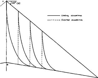
We now proceed to consider some flows where the pressure field may be such that flow separations may occur. An interesting example is the flow over the Townend surface (see Figs. 3.10 and 3.11), where the pressure behind the compression waves is not uniform so that the boundary layer development differs essentially from that along a flat plate. This boundary layer is remarkable in that it develops spanwise crossflow components even though the external streamlines are straight in plan view, because there are spanwise pressure gradients. J C Cooke & О К Jones (1964) have obtained an approximate solution for the laminar boundary layer along a Townend surface. The threedimensional flow in the boundary layer is still relatively simple because of the conicality of the flow about the tips of the compression surface. In particular, the limiting streamlines in the surface cross each ray from the tips at the same angle. Thus they all curve outwards as indicated in the example shown in Fig. 8.21. This curvature leads, in the first place, to a possible sweep instability of the laminar boundary layer, as discussed above. In the second place, separation may occur because the pressure field
|
Fig. 8,21 Streamlines over a Townend surface at Mq = 6.8. After Cooke and Jones |
 |
 |
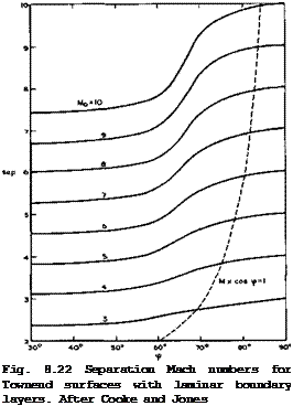
is wholly unfavourable, in the sense as defined by E C Maskell & J Weber (1959), because the pressure rises streamwise and inwards. If separation occurs as a consequence of the limiting streamlines forming an envelope, this separation line must lie along a ray from the tips, in this particular flow. Although the crossflow is not normally small near the separation line, the calculation has been carried through to separation and a Mach number, Msep, has been determined down to which the flow can be retarded before separation occurs for given mainstream Mach numbers, Mq, and angles of sweep, ф, of the line where compression begins. An example is shown in Fig. 8.22. We
find that very highly swept initial compression lines in a conically subsonic flow regime appear to lead to early separation of the laminar boundary layer, whereas a useful amount of compression may be obtained if the initial compression line is not so highly swept. For instance, with an initial Mach number of 10, a compression down to about Mj = 7.5 may be obtained, corresponding to a compression ratio of about 6.6. The separation Mach number is not directly related to that obtained in the corresponding twodimensional flow, as it is in the case of swept wings. The corresponding twodimensional values appear here as the limit ф •+■ 0 . These results have not yet been subjected to experimental tests, and the behaviour of turbulent boundary layers is not known.
Actual flight vehicles may have many regions of high compression that can cause boundary-layer separation and, possibly, reattachment. These are of special interest because of the very high heating rates that may arise locally. In a conventional layout with distinct wings, fuselage, engines,
and control surfaces, such regions include deflected flaps, shock interactions in inlets, blunt fins or other protuberances on fuselage or wing, axial comers in inlets, wing-body and wing-fin junctions, and such regions at the leading edge of wing and fins, which are subjected to the impingement of shockwaves from the fuselage or other forward components. Note that all these interactions must be expected to be highly threedimensional. An extensive review of these problems and of available methods for predicting and for dealing with these effects has been given by R H Korkegi (1971) who concludes that, in the final analysis, the severity of heating caused by viscous interaction may be such that it is far more desirable to design around them than to attempt to cope with them through weighty replaceable ablation shields or equally bulky and sophisticated forms of cooling. This is another strong reason why we want to concentrate here on design methods for integrated wave – rider shapes, where many of these interference problems do not occur. But not all of them can be avoided altogether, and one that has to be faced is that introduced by the deflection of control surfaces and attendant flow separations.
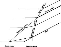
Separations induced by a sudden change in the inclination of a wall have been studied for a long time, mostly for twodimensional flows. The change in flow direction is communicated through the boundary layer upstream of the comer and may induce a separation of the boundary layer and subsequence reattachment. This flow is somewhat related to the flow in Fig. 4.64, where a shockwave interacts with a boundary layer, but here the prescribed directions of the wall constrain the flow more firmly. The simplest model of a twodimensional flow, where the result of the separation is a bubble, is sketched in Fig. 8.23. All the streamlines and also the surface of separation are
|
Fig. 8.23 Schematic model of a flow near a corner |
assumed to be straight, as are the shockwaves. There is at least one upstream shock, adjusting the flow to the change of direction near the separation line, and one downstream shock, adjusting the flow near the attachment line. These two branches intersect and continue as a single main shock into the stream. The flows that pass on either side of the intersection line should suffer the same pressure rise and the same overall change in direction, but it cannot be expected that the actual velocities should also be the same. Therefore, a shear layer or vortex sheet must be introduced downstream of the intersection line. This type of flow has been studied theoretically and experimentally by F Wecken (1949) and N H Johannesen (1952), and E Eminton
(1961) has shown that a solution for a simple flow as in Fig. 8.23 exists only for a very limited range of Mach numbers – for each angle. She concluded from her experiments that the actual flow remains similar to that in Fig.
8.23 but that it is determined by the viscous effects around the feet of the branches, and that the external inviscid part of the flow appears to be able to accommodate itself readily by small deviations from the simplified model. This means that we must expect that Reynolds number and Mach number have strong effects on this type of flow, including conditions for the pressure rise needed to cause separation. This flow is also related to flows up a step or down a step and to base flows, which have already been discussed in section 5.9. All these have been extensively investigated, experimentally and theoretically, and there are various criteria for incipient separation to occur, depending on the initial state of the boundary layer, and for estimating the development of the separated flow. We mention here the work of M J Lighthill (1953), D R Chapman et at. (1957), J C Cooke (1963), L Lees &
В L Reeves (1964) and J M Klineberg (1969). P Carrifere et al, (1975) have given an extensive summary of the various methods for calculating turbulent separated flows. In the end, however, we must rely on experimental data, especially when threedimensional effects play a part. Valuable results for the pressure and the heat transfer in separated and reattached flows at relatively low Mach numbers (up to 4) have been obtained by J Picken (1960) by means of the free-flight technique (see also J Picken & D Walker (1961)).
Out of the many other experimental investigations we refer here to the systematic work done on turbulent boundary layers at Mach numbers between 3 and 9 carried out at the Imperial College. This work has been summarised by J L Stollery (1975) who also reviews earlier theoretical and experimental developments in this field. The work includes tests by G T Coleman et al.
(1971) and (1973) on attached boundary layers along flat plates, which showed that the method of H H Fernholz (1971) gives the most reasonable overall prediction, although it gives the opposite trend of skin friction with wall temperature ratio to that generally accepted. A comprehensive and critical assessment of the accuracy of all the available prediction methods is still outstanding. Further tests by D M Rao (1970) and (1975), G M Elfstrom (1972), G T Coleman & J L Stollery (1972), and A J Edwards (1975) are concerned with attached and separated flows in compression corners and include tests on delta wings with trailing-edge flaps on the lower surface, deflected downwards.
A schematic summary of the various effects of the Reynolds number on the flow characteristics is shown in Fig. 8.24. Only the separation and reattachment shocks are shown; at higher Mach numbers, their intersection may not be relevant to the viscous flow near the comer. This diagram indicates again how important transition is in these flows. As an example, Fig. 8.25 shows the heat transfer on a delta wing with flap, which is to be compared with the results for the plain wing in Fig. 8.18. The heat transfer rises steeply in the separated region and reaches a peak near the attachment line. When the flow is turbulent, the heat transfer reaches a plateau in the separated region and then rises rapidly again to a peak near reattachment. This peak heat-transfer rate may exceed the value at the stagnation line in twodimensional laminar flow. The pressure distribution which determines – the control forces and moments achieved by the deflected flap, follows a curve which is closely similar to the heat-transfer distribution, again with a high peak near the attachment. We note from Fig. 8.25 that theoretical estimates for twodimensional flow give a rough qualitative indication of the heat – transfer levels along the centre line of the wing, but significant
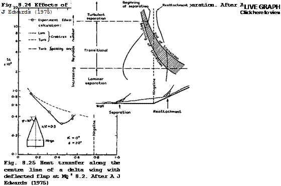 |
threedimensional effects have also been observed. For a critical review of the various criteria put forward to predict initial separation in laminar and turbulent boundary layers subjected to weak and strong interactions with shockwaves we refer again to J L Stollery (1975). One of his conclusions is that an oblique shockwave penetrates well into the boundary layer, and that
it is convenient to divide the layer into an outer, primarily inviscid but rotational, zone and a thin inner viscous layer, as in the flow model proposed by G M Elfstrom (1972).
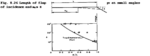
These flap-induced flow separations are so important because their upstream influence can extend very far. This can be seen from the examples in Fig.
8.26 from tests by L Davies (1970), D M Rao (1970) and (1975), and A J Edwards
(1975) , where x = xs. The difficulties in predicting this become apparent from the spread of the data, with no obvious systematic trends.
 |
LIVE GRAPH
Click here to view
Similar separations have been observed in axisymmetric flows when a flare is put on a body of revolution. According to D И Kuehn (1961) and G T Coleman &
J L Stollery (1974), the deflection angle to cause incipient separation is slightly higher in axisymmetric flow than in twodimensional flow. There is again a close similarity between the surface-pressure and heat-transfer-rate distributions in the two cases. This suggests that criteria evolved from the large amount of information available for these relatively simple flows may be used as a guide in the design of control surfaces for hypersonic vehicles.
We mention that attempts are being made to deal with more complex flows in a unified manner (see e. g. R N Gupta & С M Rodkiewicz (1975)) and to treat unsteady flows (see e. g. D Rues (1973) and W Schneider (1974)).
There is very little evidence about viscous effects and especially aerodynamic heating on the lee side of lifting bodies. Windtunnel tests by H Thomann
(1962) and free-flight tests by J В W Edwards (1965) and by G H Greenwood (1968) on delta wings with nominally subsonic and supersonic leading edges were all made under flow conditions where vortex-sheet separation from the leading edges occurred. It was found that the magnitude and distribution of heat-transfer rates to the surface follow again very closely those of the local surface pressures. The method of L F Crabtree et alm (1965) can be applied to predict heat transfer quite successfully if local flow conditions,
derived from the measured local pressures, are used. If the same method is applied, using flow conditions appropriate to the free stream, then measured values lie well below those calculated for the corresponding flat plate, especially in the region underneath the vortex sheets; they come nearer to these values in the middle region between the attachment line. Generally, the peak heating rates decrease with increasing sweepback angle but the rates near the leading edge increase. Vortex-type flows were also observed by A H Whitehead Jr (1970), D M Rao (1971), and D M Rao & A H Whitehead Jr (1972), but the implications are not yet clear.
We digress now to consider very briefly another possible application of the waverider design principle: that is to vehicles suitable for lifting re-entry into the atmosphere and, in particular, to space shuttle orbiters. This application was proposed by L H Townend (1970) and has been supported by theoretical work by L C Squire (1971) and (1975) and put to the test in many experimental investigations, e. g. by L Davies et at. (1971), R Houwink (1972)
В E Richards (1973), G T Coleman (1973), R W Jeffery & J К Harvey (1974), and R J Stalker S J 1 Stollery (1973) and (1975). The tests were carried out at high Mach numbers and very high angles of incidence, appropriate to lifting re-entry conditions. The waverider shapes with sharp edges and recessed undersurfaces are exactly opposite to the convex shapes with highly rounded leading edges commonly thought suitable for this purpose. The main advantage of bodies with recessed undersurfaces stems again from the fact that the flow may be contained and crossflow and spillage around the edges prevented or reduced. This means that, during re-entry itself, substantially higher lift coefficients (both per unit lift-to-drag ratio and maximum lift) can be generated as compared with, say, a flat-bottomed delta wing. This may lead to lower rates of heat transfer since deceleration may occur at higher altitudes so that, for a given flight speed, ambient and local air densities are lower. In addition, it has been found that the heat transfer to the waverider is less than that to the delta wing, from which it was formed, under similar flow conditions, by up to about 30Z at Mq = 20 (R W Jeffery &
J К Harvey (1974)). The theory of L C Squire (1967) gives good answers and, when suitably applied, can provide good predictions also of results obtained in high-enthalpy flows by R J Stalker & J L Stollery (1975) in a Stalker-Tube where significant non-equilibrium effects could be measured. The waverider may also offer better manoeuvrability and, after re-entry, it may glide hypersonically at higher lift-to-drag ratios than bodies of other shapes and thus improve the range and the cross-range. We already know that we can expect good flying characteristics at low speeds*. In his designs, L C Squire
(1975) has shown how extreme caret shapes may be avoided and how more practical layouts may be obtained and further aerodynamic advantages gained by going to curved concave lower surfaces. When such bodies are put into a free molecular flow, multiple interactions of the diffusely reflected molecules occur since any point on one side of the lower surface can be seen from any point on the other. Explicit solutions for the flowfield of neutral atoms have been given by W Wuest (1975) and applied to caret wings. The waverider design principles have not yet been applied in practice.
The acute heating problem of hypersonic vehicles has led to an intensive search for means of cooling the surfaces. Aerodynamically, this can be
* We may note that the wings of a shuttle will still have a high temperature when they land on return. Windtunnel tests by J F Marchman III (1975) indicated that such heating may increase the drag of the wing; but no effects were detected on the development of the leading-edge vortices nor on lift and pitching moment.
achieved very effectively by injecting cool air or some other gas into the boundary layer. This can be done in various ways: by injecting a secondary gas through one or more slots into the mainstream (film cooling); by injecting a secondary gas through a porous surface (transpiration cooling); or by the gaseous decomposition products of ablating materials (ablation cooling).
In every case, the injection of a cool gas into the boundary layer not only cools the surface but also reduces the skin-friction coefficient. But this does not imply that the drag is necessarily reduced: by injection, or suction, the overall drag of a turbulent boundary layer may be higher than that caused by skin friction alone, as has been shown by J В Edwards (1961).
Many of the available theoretical and experimental investigations of turbulent boundary layers with fluid injection have been reviewed by L 0 F Jeromin
(1970) who gave an extensive list of references which is not repeated here.
 |
|||
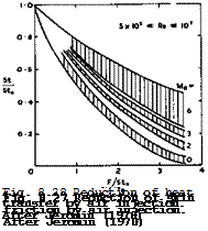
We reproduce in Figs. 8.27 and 8.28 some of his collections of typical experimental results for the reductions of skin friction and of heat transfer by air injection through a porous surface, where the shaded areas give a rough indication of the experimental scatter. The parameter
is a measure for the rate of injection. These reductions can be quite substantial. It should not be deduced from this particular way of plotting the results that fluid injections becomes less effective with increasing Mach number: for example, a plot of Cf/Cfo against F gives very roughly about the same reduction of the skin-friction coefficient due to injection independent of the Mach number. Jeromin also discusses work on the injection of gases other than air. The injection of a light gas, such as helium, gives much bigger reductions of skin friction and of heat transfer because the smaller molecular weight leads to the formation of a layer of reduced density and viscosity close to the wall. In such layers consisting of different gases, diffusion processes and their measurement present additional problems. These have been investigated e. g. by W Wuest (1962), E Krause (1966), S V Patanker & D В Spalding (1967) and E Krause et al. (1972), where a detailed discussion of theoretical and experimental results may be found. Other work by P A Libby (1962), A Kumar & A C Jain (1973), and К Gersten & J F Gross (1973) deals with various other aspects of mass injection. The work of F L Fernandez & L Lees
(1970) is especially concerned with the effects which the finite length of a twodimensional flat plate with distributed injection may have. A special problem arises from the fact that, if the conventional boundary-layer assumptions of constant pressure throughout are made, a particular value of uniform injection rate exists, beyond which no theoretical solutions can he obtained, as has been shown by 0 Catherall et al. (1965). Fernandez & Lees employ the method of В L Reeves & L Lees (1964) to demonstrate that, as injection is increased, the velocity profiles become inflected, the sonic line moves away from the wall, and the flow becomes subcritical. The effect of termination of injection can then be felt upstream of the end of injection. In particular, as injection rates approach the maximum value which can be entrained by a constant-pressure mixing layer, virtually the entire blowing region experiences a falling pressure due to the effect of finite length. This effect provides for a smooth transition from a boundary-layer flow to one where mixing is negligible, except in a thin layer near the streamsurface which divides the injected and the mainstream gas. The general prospects for the active cooling of hypersonic transport aircraft have been reviewed by J V Becker (1971).
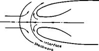
Another powerful means of cooling is the ejection of a stream of gas out of the ТЮ8Є of a blunt body, where cooling is most needed. The flow is similar to that discussed in section 5.2 in connection with Fig. 5.5(a) and its main feature is the supposed existence of a free stagnation point upstream of the orifice. The aim is at designing shapes which allow a steady flow like that sketched in Fig. 8.29 to be maintained: the ejected gas is to remain attached to the surface and turned through about 180°: the free stagnation point should remain in a fixed position in the subsonic part of the flow behind the
|
Fig. 8.29 The model of Eminton for the flow out of a forward-facing orifice |
detached curved shockwave typical of blunt body flows. It is instructive to follow the steps which have been taken in the aerodynamic design of such shapes to reach this aim, at least in part. In early experiments by H M McMahon (1958) and CHE Warren (1958), the flow was found to be highly unsteady because the ejected gas separated from the wall of the orifice and formed a jet. Where the jet reattached to the surface, the heat transfer was high, as to be expected. McMahon put a nearly vertical ‘deflector cap’, upon which the stagnation point could rest, upstream of the orifice and successfully steadied the flow, in a manner similar to the effect of the horizontal ‘splitter plates’ of D M Heughan (1953) in the region of a rear stagnation point. However, this only shifted the problem to that of cooling the cap. Warren put swirl into the flow in the ejection pipe, which caused less disturbance to the mainstream but did little to reduce the temperatures around the nose. S H Lam (1959) realised that the walls should be shaped so as to avoid large adverse pressure gradients and separation. He devised a method for calculating shapes along which the pressure is constant and equal to the undisturbed pressure in the incompressible mainstream. This is obviously an extreme and restrictive condition, and it was E Eminton (1960) who developed a more general method for obtaining shapes where the pressure remains constant at a prescribed value along the curved part. The calculation uses a hodo – graph method and is a counterpart, to that of designing constant-pressure air intakes, as discussed in section 3.7 (see Fig. 8.13). Eminton’s method is restricted to inviscid twodimensional flows, and it was expected that the gas ‘ would maintain an approximately constant pressure around these contours in the face of two alternative mainstreams – one flowing slowly enough to be considered incompressible, the other fast enough to be hypersonic. M G Hall
(1963) has followed up Eminton’s work and W Wuest & H von Trotha (1964) have extended it to cover flows where the density and the molecular weight of the ejected gas are different from those of the mainstream. They also calculated the shape of the interface between the two gases, and this enabled W Wuest
(1966) to calculate effects of viscosity, including those of thermal diffusion, by deriving exact solutions of the Navier-Stokes equations. Thermal diffusion has only a small effect if a light gas (like helium) is ejected at a lower temperature than the heavier air in the mainstream. For a heavy gas, thermal diffusion is the stronger the greater the temperature difference.
These design methods have been successful in that experiments, e. g. by L M Tucker & M G Hall (1963), P J Finley (1965), and J Reid & L M Tucker (1968), on bodies of revolution and on unswept and swept leading edges with Eminton’s calculated contours demonstrated that attached flow in the manner of Fig. 8.29 can, in fact, be achieved under certain conditions, ejecting air or CO2 . But the actual pressure distributions were, in general, not the same as those calculated. To achieve agreement, it would seem necessary to take account of the mixed nature of the flow. When the ejected mass flow exceeded certain limiting values, the flow separated and formed a forwardfacing jet. These flows with subsonic and with supersonic jets have been studied extensively by E P Sutton & P J Finley (1964) and by P J Finley (1965) and (1966), who developed an analytical model of the flow involving a separation bubble and subsequent reattachment. Even this flow may be steady in the region around the free stagnation point, and Finley derived a sufficient condition for steady flow to be obtained. Another aspect of these flows is that of the thrust and drag forces associated with them. Since the gas ejected forwards is ultimately turned downstream, it should produce a forward thrust on the body equal to that which would be obtained if the same gas were ejected directly downstream, provided the turning is accomplished isentropic – ally. Hall has derived a relation for the ideal thrust recovery, and Tucker
has measured similar values in some of his experiments; in some cases, he found thrust values even higher than the ideal – this may be explained by the fact that the actual axial force includes a wavedrag component which is related to the shape of the detached shockwave: a separated flow with a bubble may effectively ‘sharpen’ the nose, and so the greatest reduction in wavedrag, or thrust recovery, occurs with the bluffest nose contours.
The investigations of flows with nose ejection have all been restricted to symmetrical arrangements and are obviously incomplete. It is not clear how such flows may be applied in the design of waverider aircraft. It would be of interest to study asymmetrical flows from swept edges of lifting bodies and also the possibility of ejecting combustible gases for the purpose of confining cooling with providing fuel for a propulsion unit further downstream.
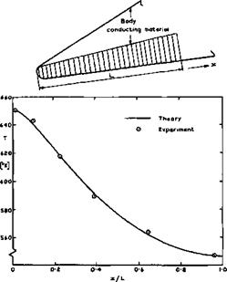
Another means of keeping temperatures down, which is probably especially appropriate to waverider aircraft, is making use of heat conduction within the structure of the lifting body. A general account of the problem involved has been given by H Schuh (1965), but here we refer to the work of T R F Nonweiler (1952), which is relevant to the design of the aerodynamically sharp leading edges, which are such a vital feature of this type of aircraft under all flight conditions, and which introduce the most severe heating problem. Simple theory would lead one to expect that the temperature at a sharp leading edge would be the so-called thermometer value, which exceeds the practical structural limits of most familiar materials at flight speeds above about Mq = 5 . This is the main reason why sharp leading edges have so far been rejected as a practical possibility and round blunt shapes adopted, which, strictly^ are aerodynamically unsuitable because they can neither contain attached shockwaves at high speeds nor fix separation lines at low speeds. Nonweiler has opened up the prospect that, by allowing a small nose radius (of the order of 1cm) and by suitably distributing conducting materials within the wing structure, the temperature can be kept within reasonable bounds, even at extreme hypersonic speeds. The general design concept is to incorporate heat conducting material along part of the leading edge, as sketched in the example in Fig. 8.30.
In his theoretical work, T R F Nonweiler (1952) and (1956) developed the model of a conducting plate, whose thickness is small but whose conductivity is large. This implies that the relative changes in absolute temperature across the plate can be ignored, and that the conductivity within the material along the surface has the dominant effect. The magnitude of the surface temperature of the hypothetical conducting plate is related to the magnitude of the heat flux into the surface. It is presumed that the surface is cooled by radiation and that, without conduction, an equilibrium state would be reached. Typically, if this equilibrium temperature is about 1200 К at a sharp leading edge, than a material of infinite heat conductivity would reduce the temperature there to about 900 К by letting heat flow away from the leading edge to other parts of the structure. Depending on the shape and size and kind of conducting material, the actual values of the temperature at the leading edge lie between these two, but the temperature at the rear of the plate is generally slightly above the radiation equilibrium temperature. Nonweiler’s theory leads to the establishment of similarity relations and to a simple approximate method for calculating the temperature distribution along the plate; the results are in good agreement with those of another method due to £ C Capey (1966); and an assessment of the optimal distribution of conducting material may be made in particular applications.
LIVE GRAPH
Click here to view
The Aerodynamic Design of Aircraft
|
Fig. 8.30 Temperature distribution along stainless steel model of a leading edge. After Nonweiler (1969) |
The theory also shows that sweepback will reduce the leading-edge temperature. On a wing of delta-like planform, the temperature will reach a maximum at the apex and also at the tips, if the geometry of the conducting surface is left unchanged along the leading edges. But these effects are slight and can readily be controlled by a locally enhanced provision of conducting material.
The calculated results have been well confirmed in suitably-designed model tests by T Nonweiler et al, (1969) and (1971). A typical example is shown in Fig. 8.30, where the material was stainless steel and had a trapezoidal shape, being twice as thick at the rear end as at the front end. Even though these investigations are not complete, we may nevertheless conclude that a modest provision of conducting material may avoid the need for a large leading-edge radius. The indications are that the associated weight penalty is not severe. Even lighter systems may be thought of: heat may be conducted away by means of ordinary heat pipes or by electro-fluid-dynamic heat pipes. These possible schemes make the prospects for waverider aircraft more realistic, but more work is needed to provide a firm basis for practical design methods.


