Experimental mean pitch
The experimental mean pitch is defined as the advance per revolution when the airscrew is producing zero net thrust. It is thus a suitable parameter for experimental measurement on an existing airscrew. Like the geometric pitch, it has a definite value for any given airscrew, provided the conditions of test approximate reasonably well to practical flight conditions.
9.3.2 Effect of geometric pitch on airscrew performance
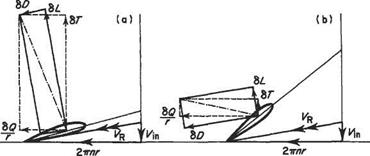
Consider two airscrews differing only in the helix angles of the blades and let the blade sections at, say, 70% radius be as drawn in Fig. 9.5. That of Fig. 9.5a has a fine pitch, whereas that of Fig. 9.5b has a coarse pitch. When the aircraft is at rest, e. g. at the start of the take-off run, the air velocity relative to the blade section is the resultant Vr of the velocity due to rotation, 2ттг, and the inflow velocity, V-m. The blade section of the fine-pitch airscrew is seen to be working at a reasonable incidence, the lift 8L will be large, and the drag 8D will be small. Thus the thrust ST will be large and the torque SQ small and the airscrew is working efficiently. The section of the coarse-pitch airscrew, on the other hand, is stalled and therefore gives little lift and much drag. Thus the thrust is small and the torque large, and the airscrew is inefficient. At high flight speeds the situation is much changed, as shown in Fig. 9.5c, d. Here the section of the coarse – pitch airscrew is working efficiently, whereas the fine-pitch airscrew is now giving a negative thrust, a situation that might arise in a steep dive. Thus an airscrew that has
|
|
|
Fig. 9.5 Effect of geometric pitch on airscrew performance |
a pitch suitable for low-speed flight and take-off is liable to have a poor performance at high forward speeds, and vice versa. This was the one factor that limited aircraft performance in the early days of powered flight.
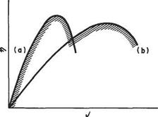
A great advance was achieved consequent on the development of the two-pitch airscrew. This is an airscrew in which each blade may be rotated bodily, and set in either of two positions at will. One position gives a fine pitch for take-off and climb, whereas the other gives a coarse pitch for cruising and high-speed flight. Consider Fig. 9.6 which shows typical variations of efficiency tj with J for (a) a fine-pitch and (b) a coarse-pitch airscrew.
For low advance ratios, corresponding to take-off and low-speed flight, the fine pitch is obviously better whereas for higher speeds the coarse pitch is preferable. If the pitch may be varied at will between these two values the overall performance
|
|
Fig. 9.6 Efficiency for a two-pitch airscrew
|
|
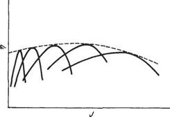
Fig. 9.7 Efficiency for a constant-speed airscrew
attainable is as given by the hatched line, which is clearly better than that attainable from either pitch separately.
Subsequent research led to the development of the constant-speed airscrew in which the blade pitch is infinitely variable between predetermined limits. A mechanism in the airscrew hub varies the pitch to keep the engine speed constant, permitting the engine to work at its most efficient speed. The pitch variations also result in the airscrew working close to its maximum efficiency at all times. Figure 9.7 shows the variation of efficiency with J for a number of the possible settings. Since the blade pitch may take any value between the curves drawn, the airscrew efficiency varies with J as shown by the dashed curve, which is the envelope of all the separate 77, J curves. The requirement that the airscrew shall be always working at its optimum efficiency while absorbing the power produced by the engine at the predetermined constant speed calls for very skilful design in matching the airscrew with the engine.
The constant-speed airscrew, in turn, led to the provision of feathering and reverse – thrust facilities. In feathering, the geometric pitch is made so large that the blade sections are almost parallel to the direction of flight. This is used to reduce drag and to prevent the airscrew turning the engine (windmilling) in the event of engine failure. For reverse thrust, the geometric pitch is made negative, enabling the airscrew to give a negative thrust to supplement the brakes during the landing ground run, and also to assist in manoeuvring the aircraft on the ground.


