Froude’s momentum theory of propulsion
This theory applies to propulsive systems of Class I. In this class, work is done on air from the atmosphere and its energy increased. This increase in energy is used to increase the rearwards momentum of the air, the reaction to which appears as a thrust on the engine or airscrew.
The theory is based on the concept of the ideal actuator disc or pure energy supplier. This is an infinitely thin disc of area S’ which offers no resistance to air
|
passing through it. Air passing through the disc receives energy in the form of pressure energy from the disc, the energy being added uniformly over the whole area of the disc. It is assumed that the velocity of the air through the disc is constant over the whole area and that all the energy supplied to the disc is transferred to the air.
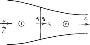
Consider the system shown in Fig. 9.1. This represents an actuator disc at rest in a fluid that, a long way ahead of the disc, is moving uniformly with a speed of V and has a pressure of po. The outer curved lines represent the streamlines that separate the fluid which passes through the disc from that which does not. As the fluid between these streamlines approaches the disc it accelerates to a speed Vo, its pressure decreasing to p. At the disc, the pressure is increased to p2 but continuity prohibits a sudden change in speed. Behind the disc the air expands and accelerates until, well behind the disc, its pressure has returned to po, when its speed is Vs. The flow between the bounding streamlines behind the disc is known as the slipstream.
In unit time:
mass of fluid passing through disc = pSV0 (9.1)
Increase of rearward momentum of this mass of fluid
= pSV0(Vs-V) (9.2)
and this is the thrust on the disc. Thus
T = pSV0(Vs-V) (9.3)
The thrust can also be calculated from the pressures on the two sides of the disc as
T = S{p2-pi) (9.4)
The flow is seen to be divided into two regions 1 and 2, and Bernoulli’s equation may be applied within each of these regions. Since the fluid receives energy at the disc Bernoulli’s equation may not be applied through the disc. Then
Po+pV2=Pi+pVl (9.5)
and
From Eqns (9.5) and (9.6)
(p*+pvi) – {pi+pvi) = {p*+pvi) – {р»+ру1)
i. e.
![]() P2~Pi=^p(V2- V2)
P2~Pi=^p(V2- V2)
Substituting this in Eqn (9.4) and equating the result to Eqn (9.3), i. e. equating the two expressions for the thrust:
X-pS{Vl-V2)=pSV, o(Fs-F)
and dividing this by pS(Vs – V) gives
Vo = {V, + V) (9.8)
showing that the velocity through the disc is the arithmetic mean of the velocities well upstream, and in the fully developed slipstream. Further, if the velocity through the disc Vo is written as
Vo = F(1 + a) (9.9)
it follows from Eqn (9.8) that
Vs + V = 2V0 = 2V(1 +a)
whence
Fs = F(l + 2 a) (9.10)
The quantity a is termed the inflow factor.
Now unit mass of the fluid upstream of the disc has kinetic energy of j V2 and a pressure energy appropriate to the pressure po, whereas the same mass well behind the disc has, after passing through the disc, kinetic energy of V2 and pressure energy appropriate to the pressure po. Thus unit mass of the fluid receives an energy increase ofl(Fs2 — V2) on passing through the disc. Thus the rate of increase of energy of the fluid in the system, dE/dt, is given by
f=rsv^(v:-r*)
![]() = PSVo(V2-V2)
= PSVo(V2-V2)
This rate of increase of energy of the fluid is, in fact, the power supplied to the actuator disc.
If it is now imagined that the disc is moving from right to left at speed V into initially stationary fluid, useful work is done at the rate TV. Thus the efficiency of the disc as a propulsive system is
TV
4~pSVo(V?-Vi)
|
k(V* + V) |
|
{V* + V) 2 [1 + {V,/V) v_ V0 1 (1+e) |

Of particular interest is Eqn (9.12a). This shows that, for a given flight speed V, the efficiency decreases with increasing Vs. Now the thrust is obtained by accelerating a mass of air. Consider two extreme cases. In the first, a large mass of air is affected, i. e. the diameter of the disc is large. Then the required increase in speed of the air is small, so Va/V differs little from unity, and the efficiency is relatively high. In the second case, a disc of small diameter affects a small mass of air, requiring a large increase in speed to give the same thrust. Thus Vs/V is large, leading to a low efficiency. Therefore to achieve a given thrust at a high efficiency it is necessary to use the largest practicable actuator disc.
An airscrew does, in fact, affect a relatively large mass of air, and therefore has a high propulsive efficiency. A simple turbo-jet or ram-jet, on the other hand, is closer to the second extreme considered above, and consequently has a poor propulsive efficiency. However, at high forward speeds compressibility causes a marked reduction in the efficiency of a practical airscrew, when the advantage shifts to the jet engine. It was to improve the propulsive efficiency of the turbo-jet engine that the bypass or turbo-fan type of engine was introduced. In this form of engine only part of the air taken is fully compressed and passed through the combustion chambers and turbines. The remainder is slightly compressed and ducted round the combustion chambers. It is then exhausted at a relatively low speed, producing thrust at a fairly high propulsive efficiency. The air that passed through the combustion chambers is
ejected at high speed, producing thrust at a comparatively low efficiency. The overall propulsive efficiency is thus slightly greater than that of a simple turbo-jet engine giving the same thrust. The turbo-prop engine is, in effect, an extreme form of by-pass engine in which nearly all the thrust is obtained at high efficiency.
Another very useful equation in this theory may be obtained by expressing Eqn (9.3) in a different form. Since
V0 = V(1 + a) and Fs = V(1 + 2d)
![]() T = pSV0(Vs – V) = pSV( 1 + a)[V( 1 + 2a) – V = 2pSV2a{ + a)
T = pSV0(Vs – V) = pSV( 1 + a)[V( 1 + 2a) – V = 2pSV2a{ + a)
Example 9.1 An airscrew is required to produce a thrust of 4000 N at a flight speed of 120ms-1 at sea level. If the diameter is 2.5m, estimate the minimum power that must be supplied, on the basis of Froude’s theory.
T = 2pSV1a{+a)
i. e.
Now T = 4000N, V = 120ms 1 and S = 4.90m2. Thus
whence
a = 0.0227
Then the ideal efficiency is
Пі 1.0227
Useful power = TV = 480 000 W
Therefore minimum power supplied, P, is given by
P = 480000 x 1.0227 = 491 kW
The actual power required by a practical airscrew would probably be about 15% greater than this, i. e. about 560 kW.
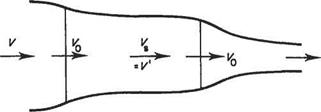
Example 9.2 A pair of airscrews are placed in tandem (Fig. 9.2), at a streamwise spacing sufficient to eliminate mutual interference. The rear airscrew is of such a diameter that it just fills the slipstream of the front airscrew. Using the simple momentum theory calculate: (i) the efficiency of the combination and (ii) the efficiency of the rear airscrew, if the front airscrew has a Froude efficiency of 90%, and if both airscrews deliver the same thrust. (U of L)
For the front airscrew, тц = 0.90 = Therefore
|
Fig. 9.2 Actuator discs in tandem and |
Vs=V(l+2a)=^V
The thrust of the front airscrew is
T = pSyVo(K – F) = Psl (j vj f) = ^pSy V2
The second airscrew is working entirely in the slipstream of the first. Therefore the speed of the approaching flow is F3, i. e. Y F. The thrust is
T = p52Tj(F’ – V) = pS2V’0(V3 – Vs)
Now, by continuity:
pS2V0 =PSlV0
and also the thrusts from the two airscrews are equal. Therefore
T = pSy V0(VS – V) = p52F'(F’ – V) = pSy F0(F’ – V3)
whence
Fs-F=F’-F5
i. e.
f; = 2F3-F=(^-i)f = HK Then, if the rate of mass flow through the discs is m:
/13 11 2
thrust of rear airscrew = m(Vs — V,) = m (——- — J V = – mF
The useful power given by the second airscrew is TV, not TV3, and therefore:
2
useful power from 2nd airscrew = – mV2
Kinetic energy added per second by the second airscrew, which is the power supplied by (and to) the second disc, is
Thus the efficiency of the rear components is
imV2
-r = 0.75 or 75% fjmV2
TV
Power input to front airscrew =
 TV
TV
0.75
 |
Therefore
Therefore


