Heat addition to airstrearns
We can now consider the third of the main elements in the design of a waverider aircraft: propulsion – *air breathing propulsionas opposed to rocket propulsion. The discussion will be restricted to selected topics. We only mention some of the many important papers on hypersonic propulsion by G L Dugger (1959) and (1960), В S Baldwin Jr (1960), R R Jamison (1962), D L Mordell & J W Swithenbank (1962),
L H Townend (1962), (1966), and (1967), S L Bragg (1963), A Ferri et at.
(1964) , M Roy (1965), L C Squire (1965), В H Goethert (1966), J W Swithenbank
(1967) , J Pike (1971) and V V Van Camp and E T Williams (1975); and some of the early theoretical work on heat addition to airstreams by H Lomax (1959),
A Mager (1959), and R E Meyer (1960). We have already briefly discussed onedimensional flow cycles with heat addition in section 3.6 and subsonic and supersonic burners in section 3.7. The need for considering combustion in a supersonic stream was demonstrated by the results in Fig. 3.16, and the need for investigating the use of new fuels, such as liquid hydrogen, in section
1.2. In view of the serious problems of future energy supplies, hydrogen may well be a suitable fuel, especially for hypersonic aircraft (see e. g.
I I Pinkel (1974), F Jaarsma (1974), G D Brewer (1974), A К Oppenheim &
F J Weinberg (1974), A Gann (1974) and W J D Escher & G D Brewer (1975)). We have shown in section 3.7 that heat addition should take place in the flow field of a solid body in order to produce a thrust force. The particular case of base burning has already been mentioned in section 5.9: various ways of burning in wakes have been proposed by J Reid & D KUchemann (1960), and experiments have been carried out by L H Townend (1963), L H Townend & J Reid (1964), and L H Townend et at. (1970) have demonstrated that stable combustion can be achieved in supersonic and hypersonic airstreams. E G Broadbent (1973) has developed theoretical models to simulate base burning, which explain the fluid-motion processes involved (see Fig. 5.83).
In this section, we shall again restrict ourselves to some of the fluid – motion aspects, which govern the main design principles. Thus we shall not deal with the many important problems which arise in connection with injecting the fuel and mixing it with the airstream and igniting it, with flame stabilisation, and with the chemical reactions that take place. Much theoretical and experimental information, especially on the structure and propagation of laminar and turbulent flames, may be found in papers by A Mestre & L Viaud
(1963) , G Winterfeld (1967) and (1968), J F Clarke & D G Petty (1970),
R Borghi (1971), F A Williams (1971), F Maurer (1972), E Krause et at. (1972),
R Lindemann (1972), W Dobrzynski & К Baumann (1974), H Rick (1974), R C Rogers & J M Eggers (1974), F Suttrop (1974), M Barrfere (1974), J F Clarke (1975),
G Dixon-Lewis et at. (1975), N Peters (1975), M Kallergis & M Ahlswede (1975) and D R Ballal & A H Lefebvre (1975). Combustion in turbulent flows has been treated by P M Chung (1969) and К N C Bray (1973). In any thermodynamic cycle calculations, the tables for air and combustion products provided in. three systems of units by M S Chappell & E P Cockshutt (1974) will be found very useful.
The work just mentioned is generally concerned with diffusion flames. Corresponding information on shoak-induaed combustion and detonation waves may be found in papers by H G Wagner (1963), P M Rubins & T H M Cunningham (1964),
F Suttrop (1965), L H Townend (1966) and (1970), L H Townend & G Joyce (1966),
H Behrens et at. (1970), F BartlmS (1971), F A Williams (1971), H F Lehr
(1972) , and I Teipel (1974). All this work has clarified many of the theoreti cal aspects, and it has demonstrated that both stable diffusion flames and also shock-induced combustion can indeed be established in supersonic and in hypersonic airstreams. Much more work is needed to develop the design technology for propelling hypersonic aircraft, but we may proceed here on the assumption that supersonic combustion is a realistic possibility.
To explain some of the flow phenomena, we follow here the theoretical work of К Oswatitsch (1959) and (1966), J Zierep (1966), (1967), and (1974), and E G Broadbent (1969), (1971), (1973), and (1976).
Consider first the steady flow with heat addition at low Mach numbers. This has been discussed in general terms by D R Chenoweth (1964), but here we can make use of some simplifications introduced by E G Broadbent (1968) in an investigation of the twodimensional flow about an electric arc transverse to an airstream. Applying the usual conservation equations, Broadbent could show that the divergence of the velocity vector arises almost entirely from changes in density through heat addition, and that ehanges in pressure are negligible. If it is assumed that the heat addition is distributed in a known manner, the resulting equations look very like the equations for incompressible potential flow past a given source distribution, and then the geometry of the streamlines also remains unchanged. But one of the equations contains an extra term which arises from the mass addition. This is because it is assumed that the additional mass is introduced with zero velocity, and part of the favourable pressure gradient is used in accelerating the new fluid up to the ambient speed, whereas sources in a potential flow are adding fluid with the ambient velocity and, therefore, experience a thrust. Thus there is only some resemblance between flows with heat addition and flows with mass addition. Further, heat addition usually introduces vorticity into the flow: consider two neighbouring streamtubes running through the same pressure gradient, one of which receives heat while the other does not; the drop in density in the heated tube will, in general, result in a higher downstream velocity so that vorticity has been created. It may be thought that, since the heated stream has been energised, it will emerge with a greater dynamic head, but this is not so: there is always a drop in the dynamic head of the heated stream. A thrust force is generated only when the heat is added inside some suitably shaped duct, as we have already seen in section 3.7 in connection with Figs.3.17 and 3.23. But this cannot be very efficient at low Mach numbers because the pressure range available for the thermodynamic cycle is so small.
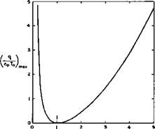
Consider now the more interesting case of compressible flows with heat addition at high Mach numbers, where we can refer to the extensive summaries of present knowledge provided by J Zierep (1974) and E G Broadbent (1975), and where further references may be found. Some instructive results can be derived for a simple one-dimensional flow with addition of mass, momentum, and energy, where a number of different flows is possible, depending also on whether Mq > 1 or Mq < 1 . For Mq > 1 , in the absence of shockwaves or detonation waves, both energy addition and mass addition lead to a decrease in the velocity, whereas momentum addition produces an acceleration; for Mq < 1 , however, the opposite is true. Generally, the effects of mass and momentum addition are of the same absolute magnitude and may, therefore, cancel one another. Solutions of the conservation equations show, in particular, that there is an upper limit to the amount of mass or energy that can be added to a steady stream and also an upper limit to the amount of momentum that can be removed from it. Thus we see again a qualitative resemblance between the addition of heat and of mass to compressible flows. If only heat is added, the maximum value of the amount of heat per unit mass turns out to be
 (8.26)
which is illustrated in Fig. 8.31. In the neighbourhood of Mq = 1 , only a small amount of heat can be added and this leads to a velocity equal to that
LIVE GRAPH
Click here to view
|
M0 Fig. 8.31 Maximum heat addition as a function of Mq |
of sound: the flow is choked. This implies, for example, that not all the curves in Fig. 3.16 can be realised, but it will be seen that this is not a severe restriction in practice. We note that, if more heat is added than that given by equation (8.26), it is no longer possible to maintain a steady flow. The resulting unsteady flows have been investigated by F Bartlma (1963) and (1971).
Although considerations of onedimensional flows reveal some important features and effects of heat addition, what we really need are design methods for twodimensional and for threedimensional flows, where heat is added continuously in the neighbourhood of solid bodies, possibly over some extended region. Before we discuss such methods in the next section, we may briefly consider the possibility of applying discontinuous flame fronts in a physically realistic manner.
Consider first a combustible mixture of a gaseous fuel and air at rest. Suppose a reaction between the two could be initiated in some plane and a flame front produced. This flame front, or deflagration wave, is a combustion process without pressure increase; it will propagate normal to itself by a process governed mainly by conduction of heat away from the flame front, which sets off new reactions. The speed of propagation of these deflagration waves is relatively low; for example, a plane flame will propagate at about 0.05m/s in a methane-air mixture and at about lOm/s in a gas consisting of 2H2 and 02 . On the other hand, the widths of the combustion zones are quite small; they are about 5 x 10“V and 5 x 10"6m respectively in the two cases quoted above. Now let such a deflagration wave be superposed upon a flowing fuel-air mixture. In general, the characteristic time and length scales implied in the chemical kinetics are quite different from those of the flow process, so that chemical kinetics and gasdynamics can be studied separately. However, in a propulsion system, the flame front should be stationary relative to the moving body, and it is difficult to think of a flowfield where the velocities are low enough to make it so in a system of reasonable size, unless extremely high angles of sweep of the flame front are contemplated, in which case the tangential velocity component along the flame front may well introduce some other mechanism in addition to heat conduction. Such a combustion process is particularly difficult to visualise in a
supersonic stream, so that deflagration waves are not very likely to find an application in hypersonic aircraft.
Next, consider the question of how chemical reactions can be initiated and maintained, at some fixed station in a supersonic premixed combustible stream of air and fuel, without changing the cross-sectional area of the stream involved. We think of a process where it is justified to assume that the chemical process is very much faster than the flow so that the characteristic length scale of the reactions is again very much smaller than a characteristic dimension of the flow. In other words we think of a process where the problems of gasdynamics can again be separated from those of chemical kinetics and where, as far as the former are concerned, the addition of heat occurs at constant area and may simply be replaced by discontinuities in some of the functions of state. A physically meaningful process of this kind is obtained if the heat addition at constant area is combined with an ordinary shockwave just upstream of it. We may then assume that the temperature rise through the shock is large enough to initiate the chemical reaction. The combination of a shockwave and discontinuous heat addition at constant area is a detonation wave. A plane detonation wave propagates normal to itself at a speed which may be as high as the speed of sound behind it, i. e. it may travel
faster than the corresponding shockwave in a non-reacting gas and is, there
fore, well suited for combustion in a supersonic stream. Its main drawback is, of course, that it can only exist in a flow which contains a combustible mixture and, therefore, a premixed stream must be provided. If the chemical kinetics of these processes are considered in more detail, it may be found that the reactions are delayed and occur some distance downstream of the shockwave. In this case, we may speak of shock-induced combustion. For our purpose, we make no distinction between such combustion and the detonation wave proper.
Some aspects of the changes of state involved in a detonation wave normal to
 |
 |
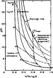
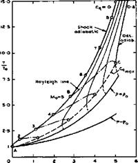
a stream with a Mach number Mq are illustrated in Fig. 8.32, where a
Fig. 8.32 Diagrams of state of a gas with heat addition at constant area
LIVE GRAPH
Click here to view
non-dimensional heat-input coefficient has been used, which is defined as
The diagrams have been drawn for an ideal gas, but this simplifying assumption is not necessary. The shockwave part of the detonation wave brings about a non-isentropic change of state from the initial conditions A to state B. The addition of heat is then another non-isentropic change from В to C along a so-called Rayleigh line. As is well-known, there is a limit to the amount of heat that can be supplied to an airstream at constant area. The maximum is reached when the Mach number behind the detonation wave is unity and this happens at the so-called Chapman-Jouguet point (shown as C in Fig. 8.32) where the Rayleigh line is a tangent to the Rankine-Hugoniot adiabatic for that amount of heat in the p, v-diagram. The Chapman-Jouguet point defines also the highest possible heat input and the dashed curves to the right of the line marked mv cannot be realised in a steady flow. Again, this does not impose a severe restriction in practice. We note that the pressure falls during the heat addition along the Rayleigh line although the overall pressure change through the detonation wave (from A to C) is a pressure rise. Comparing flow cycles with detonation waves and constant-area combustion with flow cycles with constant-pressure combustion (see section 3.6), for the same Mach number, compression, and heat input, we note that the pressure immediately behind the detonation wave is considerably lower than that behind constant-pressure combustion and that the temperature there is also less. However, temperatures and velocities at the end of the flow cycle, in the ‘jet’, are much the same in both cases and consequently also the thermal and propulsive efficiencies. The widening of the stream tube due to heat addition is also much the same in both cases.
Details about these matters may be found for instance in J Zierep (1974) and D Ktlchemann (1965), where oblique waves are also discussed which are more relevant to hypersonic propulsion than the normal waves assumed in Fig. 8.32. As in the case of plain shockwaves, only the velocity component normal to the wave front is changed and the tangential component remains the same, the normal component following the rules of onedimensional flows. With К Oswatitsch (1966), we may make a distinction between nominally subsonic and supersonic plane wave fronts, in a supersonic mainstream, depending on whether the front is more highly swept or less swept than the Mach lines. This distinction is analogous to that made in wing theory, as discussed in section
6.3, equation (6.37). Subsonic fronts have an upstream influence up to the relevant Mach line, and the normal velocity component can be increased or decreased, depending on the heat input. Thus the velocity vector may be turned either way, away from the mainstream direction. The normal velocity component is always decreased by a supersonic front, so that the velocity vector is turned towards the front. J Zierep (1967) has given an interesting relation for the change of the velocity component Vx in the mainstream direction, which holds for both subsonic and supersonic wave fronts, swept through an angle ir/2 – a :
 (8.28)
The first term on the right-hand side is the well-known Ackeret term for shockwaves without heat addition. This demonstrates very clearly the effects
which the various parameters have, bearing in mind that – 1 = cot u,
where у is the Mach angle as defined by equation (3.43) and Fig. 4.66.
In general, however, detonation waves do not exist in midair but are anchored to a wait at some point where the slope changes appropriately. Therefore, we shall continue this discussion when we come to complete flowfields in the next section.
Work is also being done on engine nacelles, on the assumption that hypersonic aircraft will be powered by separate propulsion units. We refer here to the interesting theoretical and experimental investigations by P Contensou et al.
(1973) , which led to a dual-mode ramjet with alternative subsonic or supersonic combustion in the same chamber. This permits one to obtain a performance near to that of a continuously adaptable ramjet for flight up to Mach numbers of 6 or 7, while retaining a fixed geometry for the air intake and for the nozzle during the whole mission. It may be possible to adapt these principles also to the integrated propulsion of waverider aircraft.


