LIFTING-SURFACE SOLUTION BY VORTEX RING ELEMENTS
In this section the three-dimensional thin lifting surface problem will be solved, using the vortex ring elements. The main advantage of this element is in the simple programming effort that it requires (although its computational efficiency can be further improved). Additionally, the exact boundary conditions will be satisfied on the actual wing surface, which can have camber and various planform shapes.
As with the previous example, this singularity element is based on the vortex line solution of the incompressible continuity equation. The boundary condition that must be satisfied by the solution is the zero normal flow across the thin wing’s solid surface:
V(<I> + Ф„) • n = 0 (12.1)
In the linearized lifting surface formulation of Section 4.5, this boundary condition was expressed in terms of a surface-vortex distribution (Eq. (4.50)) as
![]() J_ Г уу(дс-дсо) + ух(у-уо)
J_ Г уу(дс-дсо) + ух(у-уо)
4л Jwing+wake [(x – x0)2 + (y~ y0)2 + z2f2 0
Note that in Eq. (12.15) the small-disturbance approximation to the boundary condition was satisfied on the wing surface projected onto the x-y plane, whereas in the following example the actual boundary condition (Eq. (12.1)) will be implemented.
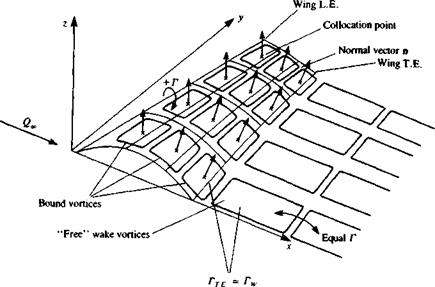
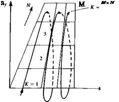
In order to solve this lifting-surface problem numerically, the wing is divided into elements containing vortex ring singularities as shown in Fig. 12.8. The solution procedure is as follows.
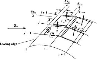
Choice of singularity element. The method by which the thin-wing planform is divided into panels is shown in Fig. 12.8 and some typical panel elements are shown in Fig. 12.9. The leading segment of the vortex ring is placed on the panel’s quarter chord line and the collocation point is at the center of the three-quarter chord line. The normal vector n is defined at this point, too. A
|
FIGURE 12.8 Vortex ring model for a thin lifting surface. |
positive Г is defined here according to the right-hand rotation rule (for the leading segment), as shown in the figure.
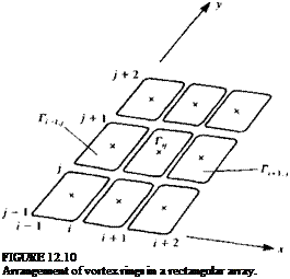
From the numerical point of view these vortex ring elements are stored in rectangular patches (arrays) with i, j indexing as shown by Fig. 12.10. The velocity induced at an arbitrary point P(x, y, z), by a typical vortex ring at location i, j can be computed by applying the vortex line routine VORTXL
|
FIGURE 12.9 Nomenclature for the vortex ring elements. |
P(X, у, г)
 (Eq. (10.116)) to the ring’s four segments:
(ult vu w,) = VORTXL (x, y, z, хц, yiJt z, ir yi/+u zu+u r, v) (u2, v2, w2)
VORTXL (x, v, z, Xf j+if уij * і• Zt j. tf x^+ij+i, Уї+ij+if
(«з. W>3)
![]() = VORTXL (x, y, z, xl+hj+l, Уі+ij+iy 2, (u4, v4, w4) = VORTXL (x, y, z, xi+] ), y,+1,y, z/+1J,
= VORTXL (x, y, z, xl+hj+l, Уі+ij+iy 2, (u4, v4, w4) = VORTXL (x, y, z, xi+] ), y,+1,y, z/+1J,
The velocity induced by the four vortex segments is then
(U, V, tv) = («!, vu W!) + (u2, v2, w2) + (m3, u3, tv3) + (u4, V4, W4) (12.16)
It is convenient to include these computations in a subroutine (see Eq. (10.117a)) such that
(и, v, w) = VORING (x, y, z, і, j, Г) (12.17)
Note that in this formulation it is assumed that by specifying the i, j counters, the (x, y, z) coordinates of this panel are automatically identified (see Fig. 12.10).
The use of this subroutine can considerably shorten the programming effort; however, for the vortex segment between two such rings the induced velocity is computed twice. For the sake of simplicity this routine will be used for this problem, but more advanced programming can easily correct this loss of computational effort.
It is recommended at this point, too, to calculate the velocity induced by the trailing vortex segments only (the vortex lines parallel to the free stream, as in Fig. 12.5). This information is needed for the induced drag computations and if done at this phase will only slightly increase the computational effort. The influence of the trailing segments is obtained by simply omitting the (иь vu w,) + (u3, v3, w3) part from Eq. (12.16):
(ы, v, w)* = {u2, v2, w2) + (u4, u4, w4) (12.18)
So, at this point it is assumed that (и, v, w)* is automatically obtained as a by-product of subroutine VORING.
Discretization and grid generation. The method by which the thin-wing planform is divided into elements is shown in Fig. 12.8 and some typical panel elements are shown in Fig. 12.9. Also, only the wing semispan is modeled and the mirror-image method will be used to account for the other semispan. The leading segment of the vortex ring is placed on the panel’s quarter chord line and the collocation point is at the center of the three-quarter chord line. The normal vector n is defined at this point, as shown in Fig. 12.9. A positive Г is defined here as the right-hand rotation, as shown in the figure. For the pressure distribution calculations the local circulation is needed, which for the leading edge panel is equal to Г, but for all the elements behind it is equal to the difference Г;-Г(_!. In the case of increased surface curvature the above-described vortex rings will not be placed exactly on the lifting surface, and a finer grid needs to be used, or the wing surface can be redefined accordingly. By placing the leading segment of the vortex ring at the quarter chord line of the panel the two-dimensional Kutta condition is satisfied along the chord (recall the lumped-vortex element). Also, along the wing trailing edges, the trailing vortex of the last panel row (which actually simulates the starting vortex) must be canceled to satisfy the three-dimensional trailing edge condition:
Yt. e. — 0 (12.19)
For steady-state flow this is done by attempting to align the wake vortex panels parallel to the local streamlines, and their strength is equal to the strength of the shedding panel at the trailing edge (see Fig. 12.8 where Гт E = for each row).
For this example (in Fig. 12.8) the chord is divided equally into M = 3 panels and the semi-span is divided equally into N = 4 panels. Therefore, the chordwise counter і will have values from 1—> M and the spanwise counter j will have values between 1—*N. Also, geometrical information such as the vortex ring corner points, panel area SK, normal vector n*, and the coordinates of the collocation points are calculated at this phase (note the panel sequential counter К will have values between 1 and M x N). A simple and fairly general method for evaluating the normal vector is shown in Fig.
12.11. The panel opposite corner points define two vectors AK and and
FIGURE 12.11
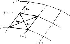 Definition of wing outward normal.
their vector product will point in the direction of nK
![]() A-к *
A-к *
|AK x BK|
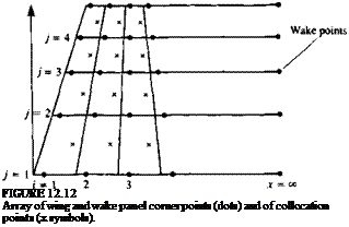
The results of the grid generating phase are shown schematically in Fig.
12.12. For more information about generating panel corner points, collocation points, area and normal vector, see the student computer Program No. 12 in Appendix D (and subroutine PANEL for the use of Eq. (12.20)).
Influence coefficients. The influence coefficient calculation proceeds in a manner similar to the methods presented so far, but in this three-dimensional case more attention is needed to the scanning sequence of the surface panels.
Let us establish a collocation point scanning procedure that takes the first chordwise row where і = 1 and scans spanwise with j = l-*N and so on (see Fig. 12.10). This procedure can be described by two “DO loops” shown in Fig.
12.13.
 |
As the panel scanning begins, a sequential counter assigns a value К to each panel (the sequence of К is shown in Fig. 12.14) that will have values from l-»Mx)V.
|
A(K, L)-U2*AL(I, J)+V2*AH(ItJ)+W2*AN(I. J) A(K, L) is influence coefficient and (AL(ItJ),AH(I, J),AN(I, J)) is the normal vector of panel (I, J) CONTINUE |
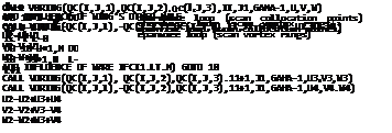 |
FIGURE 12.13
Example of a double “DO loop” to calculate the influence coefficients of a vortex ring model.
Let us assume that the collocation point scanning has started and K = 1 (which is point (i = 1 ,j — 1) on Fig. 12.12). The velocity induced by the first vortex ring is then
(m„ Vi, иОп = VORING (x, y, z, і = 1, j = 1, Г = 1.0) and from its image on the left semi-span
 |
|
(m„, vih w,,),, = VORING (x, – y, z, і = 1, j = 1, Г = 1.0)
and the velocity induced by the unit strength Г, and its image at collocation
point 1 is:
(и, v, w)n = (и, + uih Vi – v„, w, 4- tv„) (12.21)
Note that the subscript ( ),, represents the influence of the first vortex at the first collocation point, and both counters can have values from 1 to M x N. Also, a unit strength vortex is used in the process of evaluating the influence coefficient an, which is
an = (u, v, w)n – n,
To scan all the vortex rings influencing this point, an inner scanning loop is needed with the counter L = 1—*N X M (see Fig. 12.13). Thus, at this point, the К counter is at point 1, and the L counter will scan all the vortex rings on the wing surface, and all the influence coefficients aiL are computed (also, in Eq. (12.21) the ( )n index means K = 1, L = 1):
aL = (u, v, w)lL • n, (12.22)
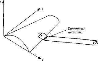
When a particular vortex ring is at the trailing edge, a “free wake” vortex ring with the same strength is added to cancel the spanwise starting vortex line (as shown in Fig. 12.15). Therefore, when the influence of such a trailing-edge panel vortex is calculated (I = M, in the inner vortex-ring loop in Fig. 12.13) the contribution of this segment is added. For example, in Fig. 12.8 the first wake panel is encountered when і = 3 (or the L counter is equal to 9). If the wake grid is added into the M +1 comer point array (as shown in Fig. 12.12 where this point is added at x = ») then the velocity due to the і = 3, j = 1 (or L = 9) panel is
(и, v, w)19 = VORING (*!, ylt zu і = 3, j = 1, Г = 1.0) and due to the attached wake
(u, v, w)l9W = VORING (xu Уг, Z, і = 3 + 1, j = 1, Г = 1.0)
|
FIGURE 12.15 Method of attaching a vortex wake panel to fulfill the Kutta condition. |
When the wing is symmetric as in this case and only the right half wing is paneled, then the (и, v, w) velocity components of the trailing edge and wake panels include the influence of the left hand side image (as in Eq. (12.21)). The corresponding influence coefficient is
fl19 = [(m, v, w)19 + (и, v, w)i9W] • n, (12.22a)
As mentioned before, parallel to the computation of the aKL coefficients, the normal velocity component induced by the streamwise segments can also be computed by using the (и, v, w)* portion as in Eq. (12.5). For the first element then
bL = (m, v, w)*L • nt (12.23)
This procedure continues until all the collocation points have been scanned and a FORTRAN example is presented in Fig. 12.13.
Establish RHS. The RHS vector is computed as before by scanning each of the collocation points on the wing:
RHSK = —Q„ • nK (12.24)
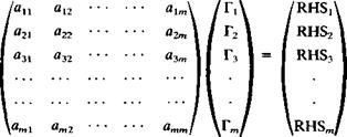 |
Solve linear set of equations. Once the computations of the influence coefficients and the right-hand side vector are completed, the zero normal flow boundary condition on each of the collocation points will result in the following set of algebraic equations:
Here К is the vertical collocation point counter and L is the horizontal vortex ring counter and the order of this matrix is m = M x N.
Secondary computations: pressures, loads, velocities, etc. The solution of the above set of equations results in the vector (Гі,. . . , Г*, . . . , Гт). If the counter К is resolved back to the original i, j counters then the lift of each bound vortex segment is obtained by using the Kutta-Joukowski theorem:
ALi< = РЄ ДГ, – r,_w) Дуц і > 1 (12.25)
and when the panel is at the leading edge (i = 1) then
![]() = РС)°£ц &У„ і = 1
= РС)°£ц &У„ і = 1
The pressure difference across this panel is
![]() (12.26)
(12.26)
where AS,, is the panel area.
The induced drag computation is somewhat more complex. The total aerodynamic loads are then the sum of the contributions of the individual panels. In this case
where the induced downwash at each collocation point i, j is computed by summing up the velocity induced by all the trailing vortex segments (see Fig.
12.5
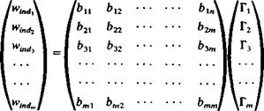 |
for the horseshoe vortex element case). This can be done during the phase of the influence coefficient computation (Eq. (12.23)) by using the VORING routine with the influence of the bound vortex segments turned off. This procedure can be summarized by the following matrix formulations where all the bK, and the Г* are known:
where again m = N x M.
The induced drag can also be calculated by using Eq. (8.146) in the Trefftz plane, through the discretization of Eq. (12.10a):
Here the counter к scans the trailing edge vortices and Nw is the number of trailing edge vortices. Since the wake is force free, the trailing vortex lines will be normal to this plane and their induced velocity wind can be calculated by using the two-dimensional formula (e. g. Eqs. (3.81) and (3.82)). If wake rollup routines are used it is recommended to calculate first the wing circulation with the rolled up wake and for this induced velocity and drag calculation to use the spacing Дy,, of the vortex lines, as released at the trailing edge. (This is the simplest approximation for a force-free wake since many wake rollup routines may not converge to this condition.)
Example: Planar wings. Consider a planar wing planform, where the leading,
trailing, and side edges are made of straight lines and the wing has no camber. By
![]()
|
|
 |
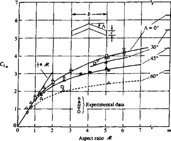
using the method of this section the lift slope CLa can be calculated and the general effect of wing aspect ratio Ж and sweep Л is summarized in Fig. 12.16. The two-dimensional values of the lift slope are shown at the right-hand side of the figure where Ж = For the two dimensional unswept wing CLa = 2л, as obtained in Chapter 5. The effect of leading edge sweep is to reduce this lift slope. Similarly, because of the increased downwash of the trailing vortices, smaller aspect ratio wings will have smaller lift slope.
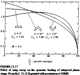
The effect of leading-edge sweep on the spanwise loading is shown in Fig. 12.17 for an Ж = 4 planar wing. Aft-swept wings will have more lift toward their tips while forward-swept wings will have larger loading near the root. This effect can be explained by observing the downwash induced by the right wing vortex on the left half-wing (Fig. 12.18). This downwash is larger near the wing centerline, and decreases toward the wing tip. In the case of the forward-swept wing, an upwash exists at the wing centerline that will increase the lift there.
From the wing structural point of view, for the same lift, the root bending moments will be smaller for a forward-swept wing than for a wing with the same aft sweep. Also for such untwisted wings the stall will be initialized at the root section of the forward-swept wing, which will create smaller rolling moments (due to possible asymmetry of the stall) than in the case of a comparable aft-swept wing. The main reason that most high-speed wings use aft-sweep is the aeroelastic divergence of the classical wing structures. (This problem can be avoided by tailoring the torsional properties of composite structures.)
Wing root bending can be reduced, too, by tapering the wing. The taper ratio A is defined as the ratio of tip to root chords:
![]() c(y =6/ 2)
c(y =6/ 2)
c(y — 0)
The spanwise loading of an untwisted wing with various taper ratios is shown in Fig. 12.19. As was noted, the load is decreasing toward the tip but the local lift coefficient (divided by the local chord) is increasing with a reduction in taper ratio. This means that the tip of such wings will stall first, an unfavorable behavior that can be corrected by twist (which reduces the angle of attack toward the tip).
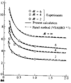
The method presented here can model ground proximity. Figure 12.20 presents the effect of distance from the ground for unswept rectangular wings. The increase in the lift slope in the proximity of the ground is present also for the smaller aspect ratio wings. In the case of the finite wing the image trailing wake
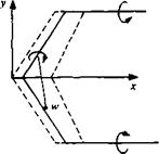 FIGURE 12.18
Schematic description of the effect of wing’s leading edge sweep.
FIGURE 12.19
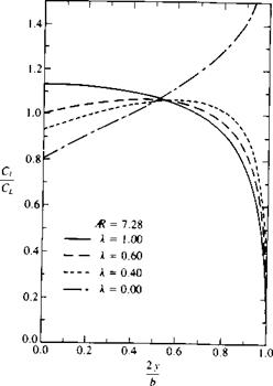
 Effect of taper ratio on the span – wise variation of the lift coefficient for untwisted wings. From Bertin, J. J. and Smith, M. L., “Aerodynamics for Engineers”, Second Edition, 1989, Prentice Hall, p. 258. Reprinted by permission of Prentice-Hall, Inc., Englewood Cliffs, N. J.
FIGURE 12.20
Effect of ground proximity on the lift coefficient slope of rectangular wings. From Ref. 13.12. Reprinted with permission of ASME.
|
FIGURE 12.21 Effect of dihedral on the lift coefficient slope of rectangular wings in ground effect. From Kalman, T. P., Rodden, W. P. and Giesing, J. P., “Application of the Doublet-Lattice Method to Nonplanar Configurations in Subsonic Flow”, Journal of Aircraft, Vol. 8, No. 6, 1971. Reprinted with permission. Copyright AIAA. |
induces an upwash on the wing that results in an additional gain in the lift due to ground proximity.
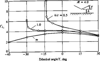
The effect of wing dihedral (see inset in Fig. 12.21) in ground proximity is shown in Fig. 12.21. Far from the ground the dihedral (as the sweep) reduces the lift slope. But near the ground, especially for negative values of dihedral (anhedral), the increase in lift of the wing portion near the ground is large, as shown in the figure.


