Quadratic Doublet Method
The method of the previous section can be further simplified by equating the source strengths to zero in Eq. (11.60). The value of the constant for the internal potential is selected to be zero and consequently the boundary condition describing the internal potential (Eq. (11.60)) reduces to
Есл + Ф. = 0 (11.81)
where Ni is the number of singularity strength parameters, and
Фоо = + W„z (11-82)
Again, note that now fi will represent the potential jump from zero to Ф„ on the boundary (see Fig. 11.26) and therefore Фи is the local total potential (whereas in the previous example ц was the jump in the perturbation potential only).
Equation (11.81) can be specified at each collocation point inside the body, providing a linear algebraic equation for this point. The steps toward establishing such a numeric solution are very similar to those of the previous method:
Selection of singularity element. The potential at an arbitrary point P due to the y’th doublet element with the three doublet parameters ц0, and ц2 is given by Eq. (11.129):
Recall that the superscripts ( )a, ( )h and ( )c represent the panel influence contributions due to the three coefficients describing the panel doublet distribution.
Discretization of geometry. The N + 1 panel corner points and N collocation points are generated in a manner similar to the previous examples (see Fig.
11.18) . In this case of the internal Dirichlet boundary condition the collocation points must be placed inside the body. This small inward displacement of the collocation point can be skipped if the panel self induced influence is specified in a separate formula.
Influence coefficients. The influence of this doublet panel is calculated exactly as in the previous section. The velocity potential at each point is the sum of all the individual panel influences and, for example, for the first collocation point due to the first panel is
(Ф>0 + Фі|Иі + Ф^2>1 = «11^01 + bllMll + C„jU,2
and the potential at this collocation point due to all the doublet panels is given by Eq. (11.131):
Фш = (aiiPoi + biiMn + Сіф21) + (<*12^02 + hi2/*i2 + C12M22)
+ • • • + (dlN^ON + bliV/l 1JV + Ctn/*2n) 3" Alwfiw (11.131)
where (iw is the constant-strength wake doublet element (as in Section 11.3.1) and A1W is the wake influence coefficient, which can be calculated by using Eq.
(11.66) . The strength of this wake doublet element is set by applying the Kutta condition at the trailing edge and is given by Eq. (11.135).
 |
||
 |
||
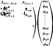
Using the backward substitution process described in the previous section the potential at the N + 1 collocation points (the additional point is inside the body and near the trailing edge) will have the form
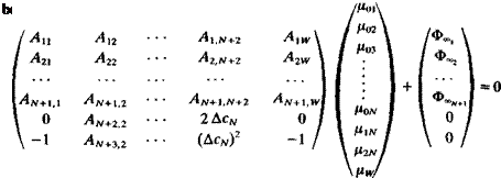
Here the last two equations are the trailing edge conditions, based on Eqs. (11.134) and (11.135) and the coefficients Alt are the result of the backward substitution as described in the previous section. Substituting this into the
(11.141)
where again the last two equations are the trailing edge conditions and are known (e. g. from Eq. (11.82)).
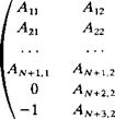
Establish RHS vector. The second term in Eq. (11.141) is known and can be transferred to the right-hand side of the equation. The RHS vector then becomes
![]() RHS, RHS2
RHS, RHS2
(11.142)
 |
and the terms are calculated by using Eq. (11.82).
 |
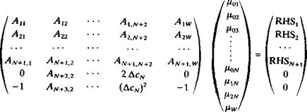
Solve equations. Substituting the influence coefficients of the doublets and the RHS vector into boundary condition Eq. (11.141) we get
(11.143)
This full-matrix equation with N + 3 unknown values fik can be solved by standard matrix solvers. Note that in this case (compared to Eq. (11.136)) the doublet represents the jump in the total potential (and not the perturbation only).
Calculation of pressures and loads. Once the values of the doublet parameters ((U01,…, n0N, HiN, h2n) are known, each panel doublet distribution can be obtained by using the backward substitution equations (e. g., Eqs. (11.134), (11.135), and (11.137)). Then the velocity at each collocation point can be calculated by differentiating the local potential,
&, = (/*„ + 2nv^) (11.144)
and the pressure coefficient can be calculated by using Eq. (11.18). The lift and pitching moment of the panel can be obtained by using the method described by Eqs. (11.78-11.80).
This method seems to involve less numerical calculations than the equivalent quadratic doublet/linear source method and therefore will require somewhat less computational time. (A computer program based on this method is presented in Appendix D, Program No. 10.)


