Rotation tensor
We have already exploited the close ties between quaternions and tensors of three space. Just glance back at the relationship between the angular velocity quaternion and the angular velocity tensor. Not surprisingly, a similar association exists between the rotation quaternion and the rotation tensor. We could make the derivation from the general rotation quaternion tensor, but prefer a simpler route. I will state the result and prove that it leads to the rotation tensor Eq. (4.12).
Given the rotation quaternion {q) in any allowable coordinate system with the scalar q0 and the vector [q, [see Eq. (4.73)], the rotational tensor [/?] in the same coordinate system is
[R] = ql[E] – [$][*][£] + 2[q][q + 2q0[Q] (4.79)
where [QI is the skew-symmetric version of q. To prove that this formulation leads to the classical form
[/?] = cos £[£] + (1 — cos є)[и][п] + sin £[1V]
we substitute the rotation quaternion = cos(£/2), [g] = sin(fi/2)[n] into Eq. (4.79)
[R] = cos2 -[£] — sin2 -(и2 + n + n^)[E] + 2sin2 ^[и][п] + 2cos ~ sin ^[JV] = cos e[E] + (1 — cos e)[n][n + sin e[1V] QED
![]()
![]()
 |
![Rotation tensor Подпись: 2{яяз + Яо Яг) 2(ягяз ~ ЯоЯ) я1~я]-я+ Яз](/img/3132/image309.gif) |
Therefore we can use Eq. (4.79) and relate the elements of the rotation tensor to the elements of the rotation quaternion. Substituting [q — q q2 q\ into Eq. (4.79) yields
 |
|
Specifically, if the quaternion {qBE}’ models the rotation of body frame В wrt Earth frame E, expressed in local-level coordinates, then its rotational tensor is [RDE’ and the direction cosine matrix
The first equation has singularities at x[r = ±90 deg, and the last equation at ф = ±90 deg. But do not despair; because these are just output calculations, you can program around them, and the accuracy suffers only in the close vicinity of the singularities.
The quaternion methodology is complete. Given the Euler angles, initialize with Eq. (4.78) the quaternion differential Equation(4.77), calculate the direction cosine matrix from Eqs. (4.80) and (4.81). Obtain the Euler angles again from Eq. (4.82), as the vehicle flies to its destination. You can acquire the detailed implementation from the CADAC SRAAM6 code, an air-to-air simulation over the flat Earth.
4.3.3.6 Summary. Here you have three methods for solving the fundamental kinematic problem of flight dynamics. You can use the archaic, compact method of Euler angles, the wasteful direction cosine matrix approach, or the elusive quaternion technique. You will need them only in full-up six-DoF simulations, where the solution of the Euler differential equations provides you with the body rates. In three – and five-DoF simulations the lack of attitude equations (Euler’s equations) makes it infeasible and unnecessary to solve the kinematic differential equations—an advantage, if these simple simulations satisfy your need.
Table 4.1 summarizes the options. I favor the latter two methods. Quaternions are well suited for the near-Earth simulations that can use the Earth as inertial frame and employ the local-level coordinate system. In this case the quaternions and the direction cosine matrix are closely linked to the Euler angles. For round and oblate Earth simulations the inertial frame is used, and the [T |,f/ direction cosine matrix is best solved directly because its angles are not the traditional Euler angles.
|
|||||||||||||||||||||||||||||||||||||||||||||||||||||
|
|||||||||||||||||||||||||||||||||||||||||||||||||||||
|
|
||||||||||||||||||||||||||||||||||||||||||||||||||||
|
|
||||||||||||||||||||||||||||||||||||||||||||||||||||
 |
|||||||||||||||||||||||||||||||||||||||||||||||||||||
|
|||||||||||||||||||||||||||||||||||||||||||||||||||||
|
|
||||||||||||||||||||||||||||||||||||||||||||||||||||
|
|||||||||||||||||||||||||||||||||||||||||||||||||||||
References
Goldstein, H., Classical Mechanics, Addison Wesley Longman, Reading, MA, 1965,
p. 118.
2Wrede, R. C., Introduction to Vector and Tensor Analysis, Wiley, New York, 1963, p. 169.
3Wundheiler, A., “Kovariante Ableitung und die Cesaroschen Unbeweglichkeitsbedin – gungen,” Mathematische Zeitschrift, Vol. 36, 1932, pp. 104-109.
4Zipfel, R H., “On Flight Dynamics of Magnus Rotors,” Dept, of the Army, Technical Rept. 117, Defense Technical Information Center AD-716-345, Cameron Station, Alexandria, VA, Nov. 1970.
5 Hamilton, W. R., “On a New Species of Imaginary Quantities Connected with a Theory of Quaternions,” Dublin Proceedings, Vol. 2, No. 13, Nov. 1843, pp. 424—434.
Problems
4.1 Orthogonality of rotation tensors. Property 4 states that the rotation tensor is orthogonal. The proof suggested using the orthogonality property of TMs. You are to develop a direct proof employing the rotation tensor.
4.2 Elevator rotation tensor. The hinge line of the elevator E is parallel to the 2B axis of an aircraft B. The deflection angle Se is measured positive when the trailing edge moves downward. Derive [RFBB, the rotation tensor of the elevator wrt the airframe, in aircraft coordinates.
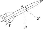
4.3 Tip speed of missile fin. A missile В executes rolling motions wrt the Earth frame E that are recorded by the onboard INS as <p(t) = cot, with со a constant. Derive the rotational tensor [/?B£((/>)]B and the angular velocity tensor [QBB]B, both in body coordinates. What is the velocity | vFB of the tip T of the control fin, which is displaced
[5їі]В = [-2 0.5 0] m
from the missile c. m. B1 The missile velocity is
[uf]B = [350 0 0] m/s
and the angular rate со — 100 deg Is (Solution: vF]B = [350 0 0.87] m/s).
1B
|
|
4.4 Tetragonal tensor is orthogonal. Show that the tetragonal tensor R9о = tin +N is orthogonal, where n is the unit vector of rotation and N its skew-symmetric form.
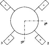
4.5 Control surface forces. A missile is steered by four control surfaces, arranged and numbered as shown in the figure, with positive deflections down as indicated. Wind-tunnel data on control effectiveness are not available, but the force /j on fin #1 was measured as a function of its deflection. If all four fins are deflected by the same amount in the positive direction, what is the total force / (missile incidence angles are zero)? Before you develop the component form, first obtain the invariant tensor.
|
4 1
|
(a) You will need the tetragonal rotation tensor K90. If b 1 is the base vector of the missile parallel to the missile centerline, show that the tetragonal rotation tensor is R90 = P + B1, where P = bb and B is the skew-symmetric form of b. Also, review the reflection tensor, given earlier M = E — 2P (see Sec. 2.3.6).
(b) Express the total force vector/ in terms of/,, /г90, and M.
(c) The force on fin # 1, with a deflection of 10 deg, was measured as [/j]f =
[—2.2 0 — 11] N in the fin coordinate system, defined by lf parallel to 1B,2F
parallel to the fin shaft and positive out, with the shaft rotated 45 deg from the 1B, 3B plane. Calculate the total force [/]B in missile body coordinates.
4.6 Missile launch. A missile M separates from and aircraft A. The attitude of the missile centerline m relative to the aircraft centerline a 1 can be expressed in terms of the rotation tensor RMA with time-dependent elements: mt = R(t)MAai. From telemetry data the yaw and pitch angles jt, в of the missile relative to the aircraft are known. Derive the rotation tensor [RMA]A in aircraft axes and calculate the instantaneous axis of rotation [nA and the rotation angle e. Is the rotation axis defined at the start of separation?
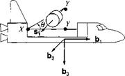
4.7 Manipulator arm. Initially, a satellite is stowed in the space shuttle bay with its symmetry axis *i parallel to the vehicle base vector b . The manipulator arm of the space shuttle deploys the satellite through an upward rotation в about the point X, followed by a rotation about point Y, that brings the satellite’s S| axis parallel and in the direction of the body base vector 62- Determine the rotation tensor [f? SB]B of the satellite frame S wrt the body frame B, in body coordinates, and the axis of rotation [n ]B and the angle of rotation ф. As a numerical example use в — 45 deg (Solution: ф = 98.5 deg, [n]B = [0.357 0.357 0.863]).
|
|
4.8 INS acceleration measurement. Before the alignment of a strap-down INS, the accelerometer triad b, 62, £3, is misaligned wrt the local-level geographic triad /], h, h, north, east, and down. The alignment errors are azimuth єф = 1.0 deg, elevation ев =0.1 deg, and roll еф = 0.05 deg. Calculate the tilt vector [erBE]L and the rotation tensor [RBE]L of the body frame В wrt the Earth frame E, expressed in local-level axes ]L. In steady horizontal flight the aircraft is subjected to the normal load factor [aL = [0 0 —1]. What are the measurements of the
three accelerometers?
|
*2 u
|
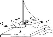
4.9 Captain’s relative motion. A boat В sails on rough water past the pier A. The linear velocity of its c. m. is v$ while its angular velocity is u>BA. The captain C is moving aft in the boat at the velocity vB. What is the velocity of the captain relative to an observer A on the pier?
|
|
4.10 Air passenger’s relative motion. A passenger P moves forward in the
cabin from point В at L m/s while the aircraft, cruising at constant speed [u£ ]B = [100 0 0] Ws, pitches up with 0(t) = 0q + 0.00It rad.
(a) Show that the velocity of the passenger wrt the Earth frame E is = Vp + SlBESPB + Vg.
(b) Calculate the numerical values of [uB]B and [uf]L if, initially, the two
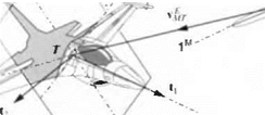
coordinate systems ]B and ]L are aligned with each other. (Solution: vE]B = [101 0 —0.001г] m/s.) 4.11 Intercept plane. As a missile intercepts an aircraft, its fuse fires near the airframe. To simplify matters, we define an intercept plane that is normal to the differential velocity vector v^r of the missile c. m. M wrt the target frame T and which contains the mass center T of the target. The miss distance of the missile is measured in this plane between T and M.
Derive the transformation matrix Tn of the intercept plane coordinates ]B wrt the target aircraft coordinates T using two methods.
(a) In the first method express the triadp|, p2, p3 of the intercept plane in ]r coordinates and thus construct [TH1. [vE1Tr and the target unit base vector f/3]7 are given in target coordinates. The intercept plane is oriented such that p, is parallel and in the direction of vTM andp2 lies in the t, t2 plane.
(b) The second method uses [i^J7 to calculate the polar angles i>pr, врт and derives T |7’7 from the two consecutive transformations ijfpj and Qpj. Calculate the numerical values of TH1 by both methods using [i)^rl7 [—500 100 100] m/s.
 |
|
V/
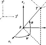
4.12 Line-of-sight rate kinematics. A radar station R tracks a point target T. The line-of-sight (LOS) displacement vector sTp is rotated from the radar’s triad ri, r2, r3 by the azimuth angle ф and the elevation angle в. We choose the inertial axes ]7 as the preferred coordinate system associated with the radar frame. For the LOS frame we define a coordinate system ]° in the following way: The 1°
direction is parallel and in the direction of Str’, the 3° direction is normal to str, lies in the plane subtended by r3, sTR, and for 0 < 0 <90 deg points toward r3.
|
|
(a) Derive the transformation matrix [T]01 of the LOS axes with respect to the inertial axes. Sketch the orange peel diagram.
(b) Derive the equation for the LOS rates u>0R that are based on the measured azimuth and elevation rates ф, 0 and express them in the inertial and LOS coordinates.
(c) Given the measured values if/ — 40 deg, 0 = 30 deg, and ф = 10 deg/s, в — 100 deg/s, calculate the numerical values for u>0R1 and [o/>R° (Solution: [ш™]’ = [64.27 -76.60 10], aP’° = [5.00 -100 8.66] deg/s).
4.13 Missile acceleration in LOS coordinates. For the formulation of an advanced guidance law, the inertial acceleration of the missile D7vj^ must be expressed in LOS coordinates d/df[u^]0. The guidance law generates the acceleration command a’M, which through the autopilot results in the acceleration of the missile. For ideal autopilots D7vj^ = a’M. Provide the individual steps that lead to the desired relationship
These are first-order differential equations in v’M° with the commanded acceleration [афм in missile axes as inhomogeneous part. We have the following frames: M = missile, О = line of sight, and I — inertial and the preferred coordinate systems ]M, ]°, ];, respectively. Point M is the c. m. of the missile.
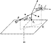
4.14 LOS rate. Flight simulators require the recording of angular LOS rates. The preferred components are 1) normal to the ground and 2) normal to the vertical plane containing the LOS. Given are the linear velocities of the missile and aircraft [uf ]L, _vR]L, respectively, and the LOS displacement [sBrL in local-level coordinates (north, east, down). Derive the equations for the angular LOS rates ш0Е and their components &>;3, parallel to the vertical unit vector/3 and oj„ parallel to the unit vector n, which is normal to the vertical LOS plane.
|
|
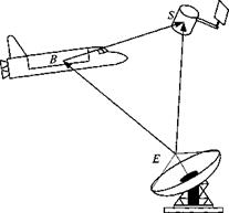
4.15 Rendezvous. The frames are the following: inertial I, Earth E, space shuttle B, and satellite S. The points are the following: location of Earth tracking station E, satellite c. m. S, and shuttle c. m. B. The coordinate systems are the following: Earth ]£, geographic ]G, and shuttle body axes ]B.
A space shuttle is sent to orbit to service a satellite. Before it can use its terminal docking radar, it must maneuver into the vicinity of the satellite. The crew uses the [Ssb]b and [vB]B displays in the cockpit to execute the approach. This position and velocity data are calculated by the onboard computer from [ssb]6, Lsbe]g, [uf ]G, and [i)g ]G that are recorded by the Earth tracking station. The orientation [ RB’B of the space shuttle wrt inertial space is determined by the onboard INS and the Earth’s orientation [f?£/]£ and transformation matrix TE0 provided by almanac tables. Your task is to develop the software that computes the displays [зд]я and [i>B]B.
|
|
(a) Obtain the tensor relationship for Ssb – For vB derive the result
vf = vf – vf + (DBR, BRiB – DER, ERiE)(sSE – sBE)
(b) Now derive the matrix equations for [.s,B]B and [uf]B, which are to be programmed for the onboard computer. As a check, I give you the velocity equation
[vBs]B = [im*£¥m£G(k]G – k£f) + (mB[RBIiB
– [^]Bt^/]£[^£/]£[f? B/]B)[[«B/]B[^/]£[7’]£G(fe£]G – srtEG)]
4.16 Rotation tensor from rotation quaternion. Derive the rotation tensors [f? i] about the axis n ] = [10 0], given the rotation quaternion
cos(e/2)
sin(e/2)[n]
Do the same for [7?г] and [/?з] with [«2 І = [010] and [«3] = [00 1], respectively.
4.17 Rotation vector from rotation quaternion. Given is the quaternion {<?} = {q0 q1 q2 q3}. Provide the angle of rotation є and the components of the unit vector of rotation [n] = n n2 n3] as a function of the quaternion elements q0, qi, q2, and q2 only. Verify that the norm of n | is one.
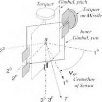
4.18 Seeker gimbal kinematics—project. When a missile comes within the acquisition range of the target, its antenna axis must be pointed at the target based on the onboard INS navigation information. Derive the equations for the seeker gimbal’s pitch and yaw angles, using the definitions displayed in the figure (the gimbal geometry is explained in more detail in Sec. 9.2.5).The INS provides the direction cosine matrix [T]BL and the LOS vector in local-level coordinates Lvb]l-
The definitions for the figure are as follows: body axes Is, 2B, 3s, outer gimbal axes 1B, 2P, 3P, inner gimbal axes Is, 2s, Зл, local-level axes ]L, yaw gimbal angle фsb, and pitch gimbal angle Osb ■
(a) Derive the equations for the seeker pointing angles Osb and фвв, which are to be programmed for the onboard computer.
(b) Given the Euler angles фвь =10 deg, ввь = 3 deg, фвь — 5 deg, and the target LOS vector [,syB] =[5 1 —3] km, calculate by hand the seeker pointing angles Osb and фвв in degrees.
(c) Program the equations for the seeker pointing angles in a subroutine INS POINT with the input arguments [T]BL and [лта]в and the output arguments 0Sb and фSB.
(d) Check your subroutine by enclosing it into a program and using the input values of (b).
(e) Use your subroutine for a second example: фвв = —30 deg, Obi, = —10 deg, фвь = — 20 deg and [swL = [2 — 1 —4] km and give the seeker pointing angles Osb and in degrees.
(f) Provide the source code listing.
|
Omtr
|
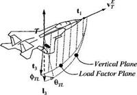
4.19 Target model—project. Missile simulations require target models of aircraft, cruise missiles, and even other missiles. These models do not have to be full six-DoF representations, but should exhibit the center of mass accelerations and the approximate attitude of the vehicle airframe. Your task is to develop such a target model and check it out in a simple three-DoF simulation.
|
Positive Load Factor
|
You model the target by its frame T and its center of mass, point T. Its orientation is described by the transformation matrix TTL of the target coordinate axes wrt the local-level axes. You can introduce a simplification by aligning the first base vector of the target t with the velocity vector vf of the target T wrt to the Earth frame E. The third base vector E points in the opposite direction of the positive load factor. The two base vectors t and E span the loadfactor plane, while the local vertical h together with 11 define the vertical plane. Both planes are separated by the bank angle фті_. You calculate the transformation matrix TrL from the three Euler angle transformations: фц, eTL ■*- фп. (heading, flight-path angle, and bank angle). The location of the target is described by the displacement vector [лу/. ]L of the c. m. of the target T from an arbitrary reference point on the Earth E expressed in local coordinates.
Three inputs generate the target maneuvers: the combined drag and thrust acceleration axc, the load factor aN(., and the bank angle фть – To simulate the time lag of the target, these three input commands are delayed by first-order transfer functions with their respective time constants Tax, Tan, Тф.
(a) Derive the transformation matrix [T]TL. Write down the nine first-order differential equations that govern the target dynamics (three input states, velocity vector Vj]L, and location vector stel)- The target maneuvers in the maneuver plane, which differs from the load factor plane by the influence of the gravity vector. Derive the equations of the maneuver bank angle фмі., which is the angle between the projections of the total acceleration vector and l3 on the plane normal to t (between maneuver and vertical planes).
(b) Code the equations for the Module G1 of CAD AC or in another simulation environment. Use worksheets.
(c) Build your own test runs for five cases: 1) straight and level flight, 2) planar climb, 3) horizontal 45-deg bank, 4) dive escape at 135-deg bank angle, and
5) launch of ballistic missile. You may also use staging (CADAC) to combine maneuvers.
(d) Document your results. Summarize the equations and add your worksheets and the code of Module G1 or your subroutine. Provide graphs of the five test cases.


