THREE-DIMENSIONAL DRAG BODIES
Among drag devices in three-dimensional flow, parachutes in particular are gaining more and more importance as decelerators for high-speed vehicles.
Plates. Since the invention of sails and kites, and certainly since Newton (1643-1727), flat obstacles were known to have a force normal to the drection of the wind, which we now call “lift”. The normal forces of disk and a square plate are shown in Chapter III of “Fluid-Dynamic Drag” up to angles of attack of 90 . The coefficient is constant between of = 50 and 140°; thus CN = 1.17 and CL = 1.17 cosof, which reduces to zero at ctf =90°. Lift fluctuations, while irregular, are not as severe as those of cylinders or plates in two-dimensional flow. The lateral-force or lift derivative of rectangular plates (6) around о = 90 is negative; it varies with aspect ratio and camber, as follows:
|
Aspect Ratio |
Camber |
CD |
dCL Idol |
|
0.2 |
flat |
1.20 |
-0.025 |
|
1.0 |
flat |
1.16 |
-0.021 |
|
5.0 |
flat |
1.20 |
-0.023 |
|
5.0 |
10% |
1.22 |
-0.029 |
It might be expected that the value of the derivative corresponds to the drag coefficient. As pointed out in (10,c) the lift-curve slope of flat “wings” around of = 90° may approximately be
dCL Idol =-CD = (ТГ/180) CD (7)
where of first in radians, and Cp^ = drag coefficient on frontal area. The results tabulated above show lift derivatives some 10% higher. Camber (10%, with the concave side against the wind) increases the lateral force considerably. This may be a consequence of shape, rather than drag.
|
|
|
|
|
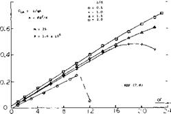
Figure 11. Lift and drag variation of bodies of revolution for range of diameter to length ratio and leading edge radius ratio. |
Bodies of Revolution. The lift of bodies of revolution with a blunt nose for length diameter ratios from.5 to 2.0 (7,d) show an increase in lift slope with increasing length, figure 11.
Here
C l_a = L/q A
where A is the maximum cross section of the model TT’d2/4. This trend is opposite to that expected based on the aspect ratio for rectangular wings, Chapter XVII, and illustrates the importance of 2 о( flow discussed in the streamline body chapter. For nose radius ratios of.05 to.2,dC /do is essentially constant. For the body with an jP/d of 0.5 the small nose radius ratio of.05 gives CL = -.2 throughout angles of attack range. For the low nose radius ratio of 0.05 and X/d of 1.0 negative values of lift are also obtained. Increasing to {/d to 1.5 and above results in a positive lift as with the very blunt leading edge. Effects of other leading edge shapes on finite bodies revolution are given in Chapter XIX.
(7) Blunt ballistic reentry vehicles:
a) Satellite Capsules, see Chapter XVIII of “Fluid-Dynamic Drag”.
b) Phillips, Blunt-faced Around ot = 90°, NAsa TM x-315 (1960).
c) Mugler, Lenticular Vehicle, NASA TM X-423 (1960).
d) Hayes, Effects of Nose Bluntness, Fineness Ratio of Bodies of Revolution, NASA TN D-650.
e) Flachsbort, Disk and Rectangular Plates, AVA Gottingen IV (1932).
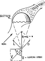
Parachutes Parachutes of the old and simple type (a fabric canopy with a man hanging underneath) were not really stable. Depending upon shape, porosity and dynamic conditions (mass, size, speed, Froude number) they had a tendency of moving in an irregular pattern of swinging, coning, circling and gliding. Lift and drag coefficients of half-spherical sheet-metal models (8,b, c,d) are plotted together in (8,a). When using these “caps” as parachute canopies, a configuration as in figure 12 is obtained. At angles of attack (wind against the plane of the rim) between 70 and 100 the lift coefficient CL. (in any direction normal to that of the wind) varies between plus and minus 0.6. The lift-curve slope is negative:
dCL /dof° = -0.024
Assuming that man or load be the center of gravity of the configuration, the negative lateral-force derivative as in the equation, readily explains that the system is not stable statically. In aerodynamic language, the moment derivative (dCm/dCL) is positive. The same goes for a drag chute as they are used to decelerate high-speed airplanes after touching ground when landing. However, since the man below a parachute descending through the air begins to move sideways as soon as the canopy assumes an angle of deflection, a complicated system of dynamic stability is set in motion involving mass and damping of man and canopy. On top of it the flow pattern in the wake of the parachute is not steady. It exhibits fluctuations of pressures and directions, at irregular frequencies. The only stable position at which the parachute might arrive is as in figure 12. At angles of attack between 40 and 50° the flow gets around the leading edge, thus producing suction and a maximum lift coefficient in the order of —1.2. It should be noted that V is larger than the sinking velocity U, and that the resultant force is larger (1.6) than the original drag (1.4). To say it in different words, the parachute is stably gliding, approximately at an angle of 45 corresponding to a ratio (L/D) = 1.
|
Figure 12. Sketch of flow pattern and forces acting upon a parachute when gliding; see also Chapter XIII of “Fluid-Dynamic Drag”. |
CIRCLE USED TO DEFINE THE SOLIDITT RATIO OF 42*
CIRCLE OF EQUAL AREA,
DEFINING THE NOMINAL DIAMETER d ** 1.16 ft
/ /
Steerable Parachutes. Parachute jumping has been developed with skydiving to the point where an experienced jumper can land within a one-meter circle from 1000’s of meters of altitude. The parachutes used for this purpose are steerable by means of an open sector (gore). The opening causes gliding; the rate of gliding depends upon the size of the opening. An adjustment of the two gore edges against each other makes the parachute turn. Both of the motions are controlled by the “pilot” with the help of his arms and hands through a pair of lines. The cross-type parachute as in figure 13 could also be steered by controlling one of the four gores. However, while one of these schemes (10,a) provides only a maximum L/D = 0.6, a more complicated configuration was developed (10,c) having an L/D ratio of 2, which is twice as high as found in optimum single-canopy designs. What we really have in this parachute is an inflated wing (Anade out of cloth) with an aspect ratio in the order of 2. Such devices are discussed in Chapter XVII.
Cross Parachute. The basic fluctuations of the wake and the instability of a parachute can be minimized by porosity of the canopy (using more or less loose fabric or a network of ribbons). Another way is shown in figure 13. The cross shape (9,b) gives the wake a regulated pattern. The moment coefficient C mo is based on developed cloth area S0 and the nominal diameter dc = S0/tT, derived from So = do TT /4. Sufficient stability about the point as in the illustration is obtained with some 30% of geometric solidity (ratio of material to open areas, “inflated” condition). The derivatives are then
|
dCmo/doT |
= -0.011 |
|
forCDo |
= 0.840 |
|
0 О >- U чз |
= +0.007 |
|
^mo / |
= -0.160 |
where Y indicates the lateral force in the canopy. This state of static stability discontinues, however, at (plus and minus) 15° away from the position corresponding to straight and vertical sinking.
Man in Free Fall. The forces and moments of a para – chutsist in free fall have been determined from wind tunnel tests (ll, a,b). These tests indicate that during “sky diving” trim is obtained only at fairly high values of angle of attack, which appears to agree with the actual results. At these high angles the best L/D of approximately 0.61 is obtained at an angle of attack of 40 ro 45 with the arms along side of the body, the legs spread at an angle of 16 and the legs bent at the hip so as to give the body camber with a negative angle with respect to the back of approximately 60°, figure 14. At this condition the lift coefficient is approximately 0.35. The lift drag ratio for the trimmed condition is 0.55.


