Calibration Apparatus
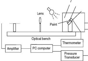
For PSP, the relationship between the luminescent intensity (or lifetime) and air pressure is determined by calibration. Figure A1 shows a simple apparatus for calibration of PSP (Burns 1995). A PSP coating is applied to an aluminum block (1.5X1.5X0.625 cm) that is thermally anchored using high thermal conductivity grease to a Peltier heater/cooler controlling the surface temperature of the block. A thermometer inserted in the aluminum block near the painted surface is used to measure the temperature of the paint sample. The PSP sample on the block is placed inside a pressure chamber with an optical access window. Pressure inside the chamber is controlled and measured using a pressure transducer. An illumination light, typically from a UV lamp, LED array or laser, passes into the chamber through the window and excites the paint sample. The luminescent emission from the paint sample is collected with a lens, filtered by a long-pass or band-pass optical filter, and projected onto a photodetector like a photodiode, photomultiplier tube (PMT) or CCD camera. The photodetector output over a range of pressures and temperatures is acquired with a PC, where the dark current is subtracted from the intensity output. Therefore, a relation between the luminescent intensity and pressure is determined over a range of temperatures; the calibration data are typically fit using the Stern-Volmer equation for different temperatures. For lifetime or phase calibrations, a pulsed or modulated excitation light should be used.
The set-up in Fig. A1 can be used for TSP calibration when the surface temperature of a TSP coating on the aluminum block is varied over a range of -15 to 150oC by controlling the Peltier heater/cooler while the chamber pressure is kept constant. Thus, a calibrated relation between the luminescence intensity and temperature is obtained, which is typically represented by the Arrhenius plot over a certain temperature range. Note that an oven for calibrating fluorescent temperature sensors was described by Crovini and Fernicola (1992). This simple apparatus can be adapted for TSP calibration down to cryogenic temperatures (Campbell et al. 1994). In this case, a TSP sample is thermally anchored to a copper bar cut at an angle of 45o at its top that rests in a container filled with liquid nitrogen. The sample temperature near the temperature of liquid nitrogen can be achieved due to heat conduction from liquid nitrogen to the sample through the copper bar. To prevent condensation of moisture from forming on the paint sample, the sample is purged with dry nitrogen gas. Using this apparatus, Campbell et al. (1994) examined the temperature dependencies of the luminescent intensity for many TSP formulations.
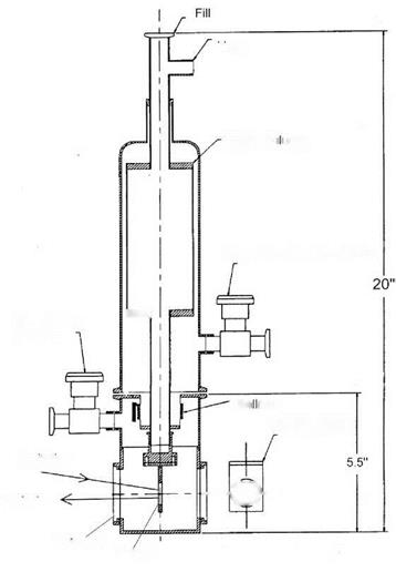
Figure A2 shows a cryostat device designed by Erausquin (1998) specially for calibrating PSP at cryogenic temperatures. Liquid nitrogen contained in the buffer volume is used to cool the device to cryogenic temperatures. A bellows is introduced between the buffer volume area of the cryostat and the test chamber area where a PSP sample is placed. Thus, the liquid nitrogen storage portion is separated from the actual test chamber into which the test gas (a mixture of oxygen and nitrogen) is introduced. Two valves are added to the lower portion to allow for filling and evacuating the test gas. There is one window on the lower portion of the test chamber allowing optical access to the PSP sample mounted on a copper sample holder. The sample holder is attached to the base of the lower tube leading from the buffer volume, allowing liquid nitrogen to directly contact with the sample holder. An aluminum sample block with a PSP coating on one surface is attached to the sample holder with an aluminum bracket and screws. The sample temperature, which is controlled by a temperature controller, is measured using a temperature sensor located above the sample holder. Absolute pressure in the test chamber is measured with an absolute pressure transducer. The luminescent emission from the paint is collected by a large lens and projected onto a PMT through a long-pass glass/interference optical filter; then, the PMT output signal is acquired with a PC. Clearly, this device can also be used for calibrating cryogenic TSP.
Vacum chamber
![]()
![]()
![]()
 Illumination source / A|uminum block
Peltier heater
|
|
|
|
|
|
|
|
|
|
|
|
|
|
|
|
|
|

![]()
Sample
Fig. A2. Calibration chamber for cryogenic PSP and TSP. From Erausquin (1998)


