Displacement Theorems
The calculation of the MOI of a flight vehicle can be a tedious process. Only in recent times has it been automated by the use of CAD programs. However, you still may be challenged to provide rough estimates for prototype simulations. You can base these preliminary calculations on simplified geometrical representations and make use of two theorems that yield the MOI for shifted reference points and axes.
6.1.2.1 Point displacement theorem (Huygen’s theorem). The MOI of body В referred to an arbitrary point R is equal to the MOI referred to the c. m. В plus a term calculated as if all mass mB were concentrated in the c. m.
Ir = І в + (®brS brE — SbrSbr) (6.5)
or in the alternate form
= (6-6)
Compare the second terms on the right-hand sides with Eq. (6.1). They are the MOI of a particle with mass mB and the displacement vector sbr between the two reference points.
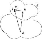
Proof: Introduce the vector triangle of Fig. 6.2
|
S iR — * IB + SBR
|
into Eq. (6.1):
IR = E nii [(Sffl + Sbs)(Si’B + Sbr)E — (SiB + SBR)(SiB + *Bfi)]
і
= E mi^iBsiBE — s,[jSat) + (sbrSbrE — sbrSrr) E tn,•
I!
+ E rtiiSiBSBR + SBS E m/Sffl – E miSiBsBR – sBR E niiSiB і і і і
The last four terms are all individually zero because В is the c. m. The first term is according to Eq. (6.1)
‘У ^ Щ / (s lBsiBE s igs їв) — І в
і
and the second term is already in the desired form of Eq. (6.5).
Huygen’s theorem helps to build the total MOI of an aircraft from its individual parts. In this case R is the point of the overall c. m., whereas В is the c. m. of the individual part. We can modify Eq. (6.5) to encompass к number of individual bodies. Let B), be the c. m. of body B^. Then the total moment of inertia I^Bk of the cluster of & bodies Bk, к — 1, 2, 3,…, referred to the common reference point/? is
lfk = E 7t + ^mBl(sBtRSBtRE – SBkRSBtR) (6.7)
к к
and its alternate form
lRBk =T,(lBBk+™BtSBkRSBtR) (6.8)
к
According to Eq. (6.6), the right-hand side can also be expressed as the sum of individual MOIs:
к
An important conclusion follows: The total MOI of a cluster of bodies B^,k = 1, 2, 3,…, referred to the reference point R, can be calculated by adding the individual MOIs, also referred to R. In most practical cases, although not mandatory, R will be chosen as the overall c. m.
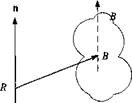
6.1.2.2 Parallel axes theorem. The axial MOI lRn of a body В about any given axis n is the axial MOI about a parallel axis through the c. m. В plus an axial term calculated as if all of the mass of the body were located at the c. m. В (see Fig. 6.3):
/fin = й/|и + mBh(sBRsBrE – sBRSBR)n (6.10)
Like any axial MOI, once the axis has been identified, it becomes a scalar with units in meters squared times kilograms.
|
Fig. 6.3 Shifted reference axis. |
Proof: Substitute Eq. (6.5) into Eq. (6.3) and obtain Eq. (6.10) directly.
Note that in Eqs. (6.5) and (6.10), the extra term can also be expressed by the tensor identity SBrSbrE – sBRsBR = SBrSBr, which is usually simpler to calculate.
Example 6.3 Tilt Rotor MOI
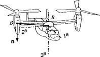
Problem. The axial MOI of the right tilt rotor is /д,, about the vertical axis [n]B = [0 0 1] (see Fig. 6.4). What is its axial MOI IRn wrt the aircraft c. m. R if the tilt rotor c. m. В is displaced by [sBR]B = sBr2 sBr,]1 What is the axial MOI of both rotors wrt R1
Solution. We apply Eq. (6.10) directly and obtain for one rotor hn = ln]B[l%]B[n]B +тв([й]в[^]ВМВ[«]В[£] – 1п]В[*вв]ВЫВ1п]в) /йзз = Ів33 + mB{slRi + 4,2 + S2m – slRl)
Irx = Івзі + mB(sBRl + sbr2)
The offset correction depends only on the square of the distance of the rotor axes from the aircraft c. m.; therefore, the axial MOI of both rotors is just twice the value
of /язз.
|
|


