Euler’s law, like Newton’s second law, must be referred to an inertial frame and, for simplicity’s sake, should be referred to the vehicle’s c. m. Yet, just as in Sec. 5.3, we ask what are the correction terms if we change to a noninertial reference frame or an arbitrary body point.. Noninertial reference frame
Shifting the reference frame from inertial I to noninertial R, but maintaining the vehicles c. m. В as reference point, incurs two additional terms in Euler’s equation. We start with Eq. (6.37) and transform the rotational derivative to the R frame:
DRlBJ + nRIlBJ = mB
The first term is modified first by replacing the angular momentum with Eq. (6.23) and introducing the angular velocity relationship between the three frames В, R, and I: u>BI — ojbr + ojri,
Dr{Ibbojbr) + Dr{Ibbojri) + nmlBJ = mB
where І вшвк = lB/ is the angular momentum wrt the frame R. Now, the two correction terms are exposed on the right-hand side of Euler’s equation:
DRlBBR =mB-nRIlBB‘- Dr(I%u>ri) (6.42)
They consist of the precession term ilRIlBB [see Eq. (6.57)] and the reference rate term Dr(Ibu>ri). For instance, if we used Earth E instead of the J2000 as inertial frame
DElf = mB – iY’l’ll – De (lBu>FJ)
the two terms —ftE, lBBI and —DE(IBu>E’) tell us whether the error is acceptable.
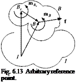
6.3.2.2 Arbitrary reference point. Euler’s law takes on its simplest form if the vehicle’s c. m. is used as reference point. Sometimes, however, it is desirable to use another point of the vehicle as reference. In Sec. 5.3.2 we used the example of a satellite with an asymmetric solar panel. It was more relevant to derive the translational equation relative to the geometrical center of the satellite Br than the c. m.
B. Now we force the attitude equation into the same mold by following Grubin.4 Beginning with Eq. (6.38), Newton’s and Euler’s equations are
mBDlDIsBI = f (6.43)
D4BB = mB (6.44)
We transform the angular momentum with the help of Eq. (6.19) to point Br
jBI vB Bl В c »~k/_
І в — * вгш ~m ^bb, D sBBr and likewise shift the moment center to Br using Eq. (6.39)
m/s = mBr – SBBrf
Both transformations are substituted into Eq. (6.44) and yield
D!{lBBrшВІ) – mBDSBBD, sBBr) = mBr – SBBJ
Applying the chain rule to the second term and using Eq. (6.43) for the last term provides
D1 (1%швг) – mB SBBrDl DlsBBr = mBr – mB SBBrDl D1sBl
Introducing the vector triangle from Fig. 6.13 and taking the rotational derivative twice,
DlD! sBl = DID, sBBr + DlD‘sBr,
and substituting into the last term provides, after canceling two terms,
Dl(lBB^BI) = mBr – mBSBBrDlD’sBrl (6.45)
We have arrived at Euler’s law referred to an arbitrary body point Br:
D1 (lBBru>BI) = mBr – mBSBBrD’v^ (6.46)
The last term adjusts for the fact that Br is not the c. m. The linear velocity v lB couples into the translational equation derived earlier [see Eq. 5.27)]:
![]()
 |
flB! flBIsBBr centrifugal acceleration +(Dl ftBI)srsB, angular acceleration
and the angular velocity и)BI connects back to the attitude equation. Both equations constitute the complete set of six-DoF equations of motion for an arbitrary reference point of body B. They are more complicated than the standard set Eq. (6.38). If Br is the c. m. B, then sBB =0; the two equations uncouple and reduce to Eq. (6.38).
Example 6.9 Physical Pendulum with Moving Hinge Point
Problem. You probably have solved this nontrivial problem before by the Lagrangian methodology. I will demonstrate here that Eq. (6.46) leads in a straightforward manner to the solution.
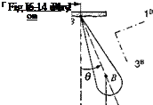
The physical pendulum with mass mB and MOI IB swings about the hinge point Br, which in turn is excited by the forcing function [,vB = [A sin cot 0 0] in inertial coordinates, as indicated in Fig. 6.14. What is the differential equation that governs the dynamics of the pendulum? The MOI is given in body coordinates
 |
[I§ ]B = [diag(/i, І2, /3)], and the displacement of the c. m. of the pendulum В from the hinge point by [sBB ]B = [0 0 /].
Solution. To solve the problem, we express Eq. (6.45) in body coordinates with the exception of the inertial acceleration:
where [®B/]B =[0 0 0], [mBr]B = [0 —mBgl sin# 0], and [d2sBr//dt2]7 = [—Aco2 sin cot 0 0]. Multiplying the matrices yields the equation of motion
hd + mBgl sin в = тв IA со2 sin cot cos в
If you have tried to solve this problem before by the conventional method, you will agree that my method is easier.
After having dealt with the more important case, namely the free-flight attitude equations, we consider point R of Eq. (6.35) to be simultaneously a point of the body and the inertial reference frame, but not necessarily the c. m. A body with a contact point on the ground, the so-called top, can serve as an example.


