Flow Separation on Wings with Highly Swept Leading Edge—Experimental Observations
The high angle of attack separated flow pattern, based on numerous flow visualizations (see Refs. 14.29-14.32) over highly swept wings (e. g., a small-zR delta wing) in terms of the crossflow is depicted in Section BB of Fig. 14.27. If the leading-edge radius is small (sharp L. E) then such L. E. vortices will be present at angles of attack as low as 10°. Because of these vortices, the actual flowfield is entirely different from what would have been expected according to the attached-flow model of slender-wing theory (Section 8.2.2). Also, when the leading edge is sharp, the location of the separation line is fixed along the leading edge, and the flowfield appears not to be sensitive to changes in the Reynolds number.
The effect of this vortical flow (leading-edge vortices) on the pressure distribution is shown in Fig. 14.41. The two large suction peaks on the upper surface of the wing are due to the high-speed flow induced by these vortices.
FIGURE 14.41
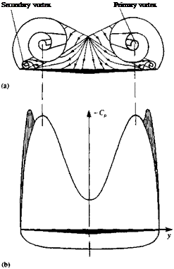 Schematic description of the primary and secondary vortex pattern (in the crossflow plane) of the flow over a slender delta wing and the resulting pressure distribution. From Ref. 14.33 published by AGARD/NATO.
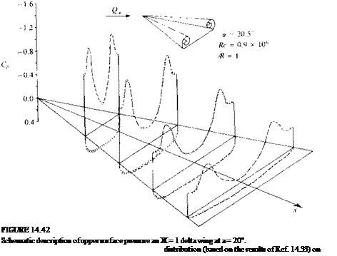
This high velocity creates a secondary shear flow near and on the wing’s upper surface and results in the presence of a secondary (and some times even a tertiary) vortex that is much smaller and weaker; its effect is shown in the figure. The above shape of the spanwise pressure distribution (see Ref. 14.33) is maintained along the chord (Fig. 14.42) but the suction force is the strongest near the wing apex. This spanwise pressure distribution is entirely different from the pressure difference data results of the linear theory in Fig. 8.21. Furthermore, the lift coefficient of the wing with leading-edge separation (up to a — 45°) is considerably larger than predicted by the linear theory (Eq. (8.94)). The difference between the linear value (of (л/2)Ака in the low angle of attack case) and the actual lift is often referred to as “vortex lift” (and shown in Fig. 14.43). So in this case of wings with highly swept leading edges, the lift is increased due to L. E. separation, unlike in the unswept wing case where the lift is reduced. This fact was realized by many aircraft designers and many modern airplanes have such highly swept lifting surfaces, called strokes (see Fig. 14.44). For example, if such a strake is added in front of a less swept back wing then the vortex originating from the strake will induce low pressures, similar to those in Fig. 14.42, on the upper surface of the main wing.
![]()
 |
|
|
![]()
FIGURE 14.44
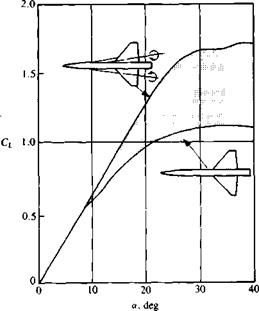 Effect of strakes on the lift of a slender wing/body configuration. From Skow, A. M., Titiriga, A. and Moore, W. A., “Forebody/Wing Vortex Interactions and their Influence on Departure and Spin Resistance”, published by AGARD/NATO in CP 247-High Angle of Attack Aerodynamics, 1978.
Therefore, the total gain in lift will surpass the lift of the strake alone, as shown in Fig. 14.44.
As mentioned earlier, in contrast to the unswept wing case, the lift of a slender wing is larger when the leading edge is sharper, as shown in Fig. 14.45 (here a — is used since there is a lift difference due to effective camber between wing A and wing B). In this case the lift of delta wing A is slightly larger than the lift of the inverted wing, and in both cases the lift is larger than in the case of a rounded leading edge. So in general, when the flow is turned more sharply (when viewed in the two-dimensional cross-section as in Fig.
14.27, section BB) the vortex will be stronger, resulting in more suction force. As the leading edge radius increases, the lift usually decreases and depends more on the Reynolds number. Also in this case of leading-edge separation, the “classical” suction force at the leading edge is lost and therefore the drag force will be larger than for the elliptic case of Section 8.2.2. Consequently, the resultant force due to the pressure difference on the lifting surface will act normal to the surface and therefore the induced drag can be estimated by
CD = CL tan a (14.19)
A more careful examination of Fig. 14.43 reveals that the highly swept wing stalls, too, at a fairly large angle of attack. This stall, though, is somewhat different from the unswept wing stall and is due to “vortex burst” (or breakdown). This condition is shown by the flow visualization of Fig. 14.46, and at a certain point its axial velocity in the vortex core is reduced and the
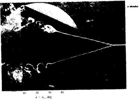
Flow visualization in water of leading-edge vortex burst. From Lambourne, N. C. and Bryer, U. W., ARC R & M 3282, 1962. Reproduced with the permission of the Controller of Her Majesty s
Stationary Office.
 |
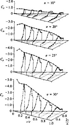 |
FIGURE 14.47
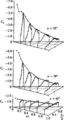
Upper-surface pressure distribution on a slender delta wing at various angles of attack and beyond stall. From Ref. 14.34. Reprinted with permission. Copyright AIAA.
vortex becomes unstable, its core bursts, and the induced suction on the wing disappears. The pressure distribution on the delta wing (from Ref. 14.34) for several angles of attack (shown in Fig. 14.47) shows this effect of vortex lift and vortex burst. So, as a result of the vortex burst the lift of the wing is reduced and a condition similar to stall is observed. Flow visualizations sometimes show the burst as a sudden spiral growth in the vortex core (see Fig. 14.46) and this is called “spiral burst”; in other instances it is seen as a bubble burst (hence it is called “bubble burst” or “bubble instability”). The onset of vortex burst was investigated by many investigators and the results for a delta wing can be summed up best by observing Fig. 14.48 from Polhamus.1435 (Incidently, Polhamus developed a method of estimating the vortex lift based on the leading-edge suction analogy and for more details the reader is referred to Ref. 14.35 or section 19.7 of Ref. 14.8.) The abscissa in Fig. 14.48 shows the wing aspect ratio, and the ordinate indicates the angle of attack range. The
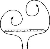
curve on the right-hand side indicates the boundary at which vortex burst will reach the wing’s trailing edge. The method of reading this figure can be demonstrated by taking the delta wing of Fig. 14.43 (Ж = 1) and, for example, gradually increasing its angle of attack. This gradual increase will cause the vortex burst, which is far behind the trailing edge, to move gradually forward. According to this figure, at about a = 35-40° the vortex burst will pass forward of the trailing edge and spoil the lift and initiate the wing stall. Also, for larger wing aspect ratios (less L. E. sweep) the burst will occur at lower angles of attack. As the wing becomes very slender the leading edge vortices become very strong and the burst is delayed. But for these wings another flow phenomenon, called “vortex asymmetry,” is observed. This situation occurs when the physical spanwise space is reduced, and consequently one vortex rises above the other (Fig. 14.49). Usually any random disturbance can cause this instability to develop and changes in the asymmetry from side to side are
 |
FIGURE 14.49
Schematic description of the crossflow due to asymmetric leaaing edge vortices.
also possible. The onset of this condition is depicted by the left-hand curve in Fig. 14.48. For example, if the angle of attack on an Ж = 0.5 delta wing is gradually increased, then over a *20° the vortex asymmetry will develop. If the angle of attack is increased, say up to a = 40°, the lift will still grow and probably near a = 45° the vortex burst will advance beyond the trailing edge and wing stall will be initiated. In general the condition of an asymmetric vortex pattern is undesirable because of the large rolling moments caused by this asymmetry. Furthermore, the pattern of asymmetry is sensitive to disturbances and can arbitrarily flip from side to side. The presence of a vertical fin (e. g., a rudder) between the two vortices or a central body (as in missiles) can have a stabilizing effect and delay the appearance of this vortex asymmetry.
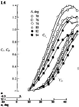
To conclude this discussion on experimental data of slender wings, a set of typical lift coefficient data is presented in Figs. 14.50 and 14.51. Note that in the data of Shanks14 36 leading-edge sweep angle rather than wing aspect ratio is presented (but for delta wings Ж = 4c tan Л where Л is the aft-sweep angle).
 Shanks, Ref. 14.36 NASA TND – 1822
FIGURE 14.50
Lift and drag coefficient versus angle of attack for several slender delta wings. (Adapted from Ref. 14.36; Re= 3.2 x 10⁵.)
FIGURE 14.51
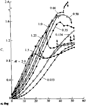 Normal force coefficient versus angle of attack for several slender flat rectangular wings. From Winter, H., "Flow Phenomena on Plates and Airfoils of Short Span,” NACA TM 798, 1937.
The lift of slender rectangular wings (Fig. 14.51) is enhanced too by the side-edge vortex lift, and the effect of the vortex lift on the wing is similar to the case of slender delta wings (mainly when wing Ж < 1, and the leading and side edges are sharp). In this case, though, the flowfield is somewhat more complex because of the presence of a leading-edge separation bubble that is noticeable for sharp leading edge wings (Fig. 14.52). This bubble is created by the time-dependent leading-edge vortex shedding (as in Fig. 14.27) but its effect is small compared to the vortex lift of the side-edge vortices (when Ж<1).
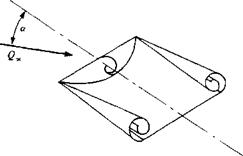 FIGURE 14.52
Schematic description of the leading- and side-edge vortex rollup on a slender rectangular thin wing.


