Grubin Transformation
Now imagine that you are in the captain’s chair of the fictional starship Enterprise. The ship’s c. m. В is far behind your location Br. Before you execute a maneuver, you want Mr. Spock to calculate the forces that you are exposed to because of your displacement sBBr from the c. m. of the spaceship.
This problem was addressed by Grubin3 and therefore carries his name. Similar to the Coriolis transformation, our goal is now to write Newton’s law wrt an arbitrary reference point Br of body В and move the additional terms to the right – hand side of the equation:
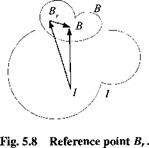
mBDIvIB = f + correction terms From Fig. 5.8 derive the vector triangle
Sfi/ = + Sfi,/
and substitute it into Eq. (5.8):
mBDIDIsBBr +mBD, D,sBri = f (5.26)
The second term is already in the desired form:
mB Dl DlsBri = mB D’vB
The first term, which will generate the apparent forces, is treated next. We will make use of the fact that DBsBBr — 0 because both points belong to the body frame В and apply the chain rule
mB Dl DlsBBr — mB D1 (DBsBBr + flBIsBBr) = mB D1 (flBI s BBr)
= mB D! nBIsBBr + mBftBI D1 sBBr = mB DIttBlsBBr + mBttBI(DBsBBr + ttB, sBBr)
= mB D! flBlsBBr + mBflBInBIsBBr
Substitution into Eq. (5.26) leads to Grubin’s form of Newton’s second law:
![]()
 |
„ , , R I nB/nBIs BB centrifugal acceleration
m D vB — / — m < R. r
’ I + (£)’ G )sBBr angular acceleration
Sitting in your captain’s chair you experience two additional forces caused by centrifugal and angular accelerations. If you move to the c. m. of the spaceship, both forces vanish as your displacement vector sBBr shrinks to zero.
Example 5.8 Satellite with Solar Array
Consider a space station with a long empennage of solar arrays (see Fig. 5.9). The geometric center of the space station Br is a more important reference point than the rather obscure common c. m. B. Grubin’s transformation shows us how to set up the equations of motion. If the space station is rotating with the angular velocity uiBI, it is subject to the centrifugal acceleration ftB, flBISBBr and the angular acceleration D! nBISBBr • To develop the trajectory equations for the geometric center, we assume that the gravitational force is given in inertial coordinates If}1 = mBg}1, as well as the angular velocity and the position vector in body axes sbr,r.
The transformation matrix [T}BI relates the body and inertial axes. Then, from Eq. (5.27) we obtain the equations of motion in matrix form:
![]()
 |
df
Another important application of Grubin’s transformation is related to the specific force measurements of an INS. Seldom is the instrument cluster located at the c. m. of the missile. To determine the corrections that need be applied to the raw measurements, we use Grubin’s transformation to express the vehicle’s c. m. acceleration in terms of the center of the accelerometer cluster. The correction terms are the centrifugal and angular acceleration terms (see Problem 5.10).
We were able to derive the Coriolis and Grubin transformations of Newton’s law in an invariant tensor form, valid in any allowable coordinate system. The last example gave an indication of the conversion process for computer implementation. In aerospace vehicle simulations you will encounter many different ways of modeling the translational equations of motions. In the next section I will summarize the most important ones, but reserve the details for Part 2.


