POSSIBLE ADDITIONAL FEATURES OF PANEL CODES
MODELING OF PROPULSION EFFECTS. Many fluid-dynamic problems involve high-energy jets where the jet speed and stagnation pressure are
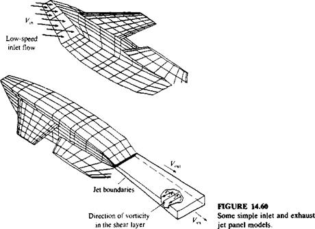
considerably higher than the corresponding free-stream values (as in the case of a jet airplane or a jet-assisted vertical take-off airplane). Even though the jet flow is compressible and its mixing process with the outer flow is highly viscous, there are several models for simulating the far-field effect of confined jets on the otherwise ‘ potential outer flow. One such model is described schematically in Fig. 14.60 and here the outer shear layer of the lifting jet is modeled by linearly varying (along the jet axis) doublet panels1211 (which are equal to a constant-strength vortex sheet). Lower-speed inlet or auxiliary exit flows can be simulated in many panel codes by simply allowing a transpiration velocity in the normal flow boundary condition, as shown for the inlet flow in Fig. 14.60. The method of including this transpiration velocity in the boundary condition is given by Eq. (14.4):
![]()
 |
Э(Ф + Ф„)
дп
but here Vn is a prescribed average jet velocity. When the Dirichlet boundary condition is used then the source term of Eq. (9.12) (e. g., in the panel code VSAERO12 n) can be modified such that
a = n • Qo„ – F„ (14.21)
The inlet model of Fig. 14.60 is useful mainly to describe the principle of specifying the inlet inflow, but for good computational results the inlet must be
|
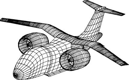
FIGURE 14.61 Detailed panel model of the tilt-nacelle airplane and its inlets, using 2546 panels per side. (Courtesy of S. Iguchi, M. Dudley and D. Ashby, NASA Ames Research Center). |
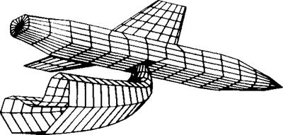
modeled with more details, as shown in Fig. 14.61. In this case the nacelle inlet is modeled in detail by a large number of panels and the inflow is specified deep inside the nacelle, near an imaginary compressor inlet disc. When the jet is ejected at a large angle to the main flow direction, then the shape of the jet centerline (Fig. 14.62) is usually calculated with the use of some empirical formula that relies on the jet initial velocity and the velocity in the potential
|
FIGURE 14.62 Panel model for the plume of the jet ejected normal to the flight direction. (Courtesy of George A. Howell, General Dynamics.) |
field into which the jet flows. Consequently, an iterative process is used in some cases in which the jet boundary is treated as a wake (see wake rollup in Section 14.1).
Since a vortex ring model results in a large velocity near the jet outer boundary and a lower velocity at the center of the jet (which is incorrect and limits the use of such models to far-field effects only), more refined jet models have been tried. One approach is to model the wake boundary by using constant-strength doublets (similarly to a solid surface) and the jet entrainment that is obtained from empirical data is modeled by a surface source distribution
|
Inflow velocity
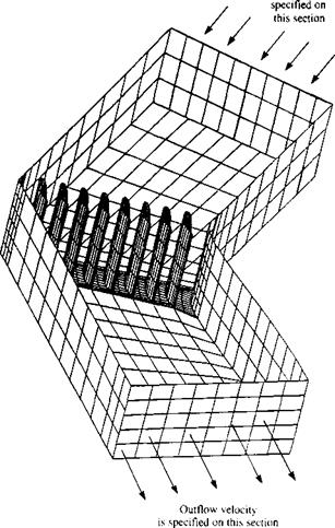
FIGURE 14.63 Panel model for the internal flow to study the aerodynamic of turning vanes inside a wind tunnel. (Courtesy of D. Ashby, NASA Ames Research Center). |
on the jet boundaries (PMARC9 6). The jet centerline shape in this case, too, can be calculated again by using empirical formulas or by a time-stepping wake rollup routine (see Section 14.1).
INTERNAL FLOWS. In a situation when internal flows are modeled as in the case of channel flows, or when studying wind-tunnel/model combined flow – fields, then some methods allow the reversal of the direction of the normal n to the surface. For example, Fig. 14.63 depicts such a situation, where the turning vane geometry inside a wind tunnel is analyzed. For the basic problem, the free-stream velocity can be specified at the inflow plane as V„ = Q«, and some other velocity at the exit plane (usually reduced by the cross-section area ratio). When the Dirichlet boundary condition is applied to the region outside of the wind tunnel, the far-field boundary disappears and the influence coefficient matrix becomes singular such that the doublet solution is unique to within an arbitrary constant (also if the free-stream is set by prescribed sources at the inlet/exit planes then the other sources will be equal to zero—according to Eq. (9.12)). This difficulty may be overcome by specifying the doublet value on one of the panels (e. g., a value of zero on the wind-tunnel inlet plane). Also, an additional equation is added based on mass conservation of the inlet and exit flows. More details about this approach are provided in Ref. 9.7.
[1] –
FIGURE 4.14
Variation of two-dimensional lift curve slope with Mach number using Prandtl – Glauert formula.
[2] A quadrilateral is a flat surface with four straight sides. A rectilinear panel has straight but not necessarily flat sides and can be twisted!
[3] For convenience, therefore, in this chapter Ф is often referred to as a perturbation potential.


