Re = 104-106
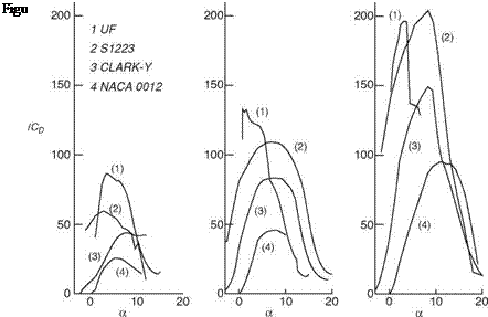
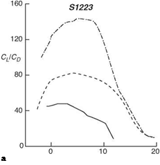
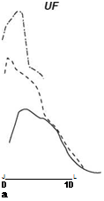
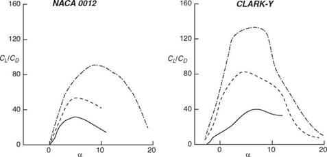
Shyy et al. [147] evaluated the aerodynamics between the chord Reynolds number of 7.5 x 10⁴ and 2 x 10⁶, using the XFOIL code [96], for two conventional airfoils – NACA 0012 and CLARK-Y – and two low Reynolds number airfoils: S1223 [148] and an airfoil modified from S1223, which is called UF (see Fig. 2.22). Figures 2.23 and 2.24 show the power index, cL/2/Cd, and lift-to-drag ratio, CL/CD, plots at three Reynolds numbers: 7.5 x 10⁴ , 3 x 10⁵, and 2 x 10⁶. It is noted that for steady-state flight, the power required for maintaining a fixed-wing vehicle in the air is
![]()

 |
 |
(2-20)
 |
where P and W are the required power and vehicle weight, respectively. For all airfoils, the CL/CD ratio exhibits a clear Reynolds number dependency. For Reynolds numbers varying between 7.5 x 10⁴ and 1 x 10⁶, CL/CD changes by a factor of 1-3 for the airfoils tested. Except for the UF airfoil, which is very thin, the range of the AoA within which aerodynamics is satisfactory becomes narrower as the Reynolds number decreases. Clearly, the camber is important. NACA 0012, with 0 percent camber, and CLARK-Y with 3.5 percent camber, yield a less satisfactory performance under all three Reynolds numbers. S1223 and UF, both with 8.89 percent camber, perform better.
Finally, NACA 0012, CLARK-Y, and S1223 all have maximum thickness of about 0.12c. The UF airfoil, in contrast, is considerably thinner, with a maximum thickness of 0.06c. It is interesting to compare the Reynolds number effect. At the Reynolds number Re = 2 x 10⁶, S1223 and UF airfoil have comparable peak performances in terms of cL/2/Cd and CL/CD; however, S1223 exhibits a wider range of acceptable AoAs. At the Reynolds number Re = 7.5 x 10⁴, the situation is quite different. UF, the thinner airfoil with identical camber, exhibits a substantially better aerodynamic performance while maintaining a comparable range of acceptable AoAs. This is consistent with the finding of Okamoto et al. [139] discussed previously.
Murphy and Hu [149] experimentally measured the aerodynamic characteristics of a bio-inspired corrugated airfoil compared with a smooth-surfaced airfoil and a flat plate at the chord Reynolds numbers of 5.8 x 10⁴ and 1.25 x 10⁵. Their measurement result revealed that the corrugated airfoil has better performance in providing higher lift and preventing large-scale flow separation and airfoil stall at low Reynolds numbers (<105) than the smooth-surfaced airfoil and the flat plate, as shown in Figures 2.25 and 2.26. However, the corrugated airfoil was found to have higher drag coefficients compared to those of the smooth-surfaced airfoil and the flat plate at low


![]()
 |
120
CJCD
80
40
0
Figure 2.24. CL/CD against AoA plots for the four airfoils [147]. —, the Reynolds number,
Re = 7.5 x 10⁴; —, the Reynolds number, Re = 3 x 10⁵; ……. , the Reynolds number, Re =
2 x 10⁶.
AoAs (<8°). The corrugated airfoil is less sensitive to the variation in the Reynolds number. Furthermore, as shown in Figure 2.26 Murphy and Hu’s [149] flow measurement suggested that the protruding corrugation corners would act as boundary-layer trips to promote the transition of the boundary layer from laminar to turbulent while remaining “attached” to the envelope profile of the high-speed streamlines.


