The coefficients
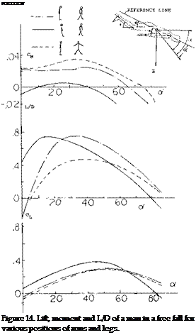
CL = L/qS, CD = D/qS, and CM = M/qS 1 where S is the area based on the man’s height Л and shoulder width. The reference length noted in the moment equation is the height. The wind tunnel test results are given on figure 14 for the man in the best position to give peak L/D as well as other typical positions of possible interest.
Based on the drag the effective aspect ratio is about one half the apparent value. The lift curve corresponds to the function 1.6 sin2o^ cosa. This value is somewhat less than would be predicted in Chapter XIX.
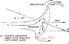
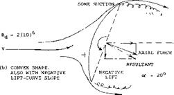
Radar Screens. Radar screens are structures similar in aerodynamic shape to parachutes. They are usually very porous; that is, their solidity ratio is small (for exampe, in the order of 40%). However, the parabolic reflector shown in figure 15 is solid.. As a function of the yaw angle/3 (measured against the center axis of the circular screen) maximum forces correspond to the coefficients (based on total fontal area, at $ = 0).
 CDo =1.08 at /3= 0°
CYo =-.41 at /$= 40°
The lateral force is negative in comparison to a positive angle of yaw. Considering flow in the opposite direction (against the convex side) maximum values are
|
CDo |
= 0.85 |
о о и 75 |
|
О -< о |
= – .14 |
at /3 = 30° |
The lateral force is negative again, evidently on account of negative “base” pressure and some suction, as indicated in the illustration.
|
|
(8) Characteristics of “cups” and “caps”:
a) See in Chapter XIII of “Fluid-Dynamic Drag”.
b) Hansen, Sheet-metal Caps, AVA Gottingen Ergebnisse Vol IV (1932).
c) Breevort, Forces on Anemometer Cupt, NACA TN 489 (1934).
d) Doetsch, Sheet-metal Parachute Models, Luftf’Forschg 1938 p 577.
e) Babish, Two-dimensional Flow Pattern, FDL-TDR-1964-136, AD-461,342.
(9) Lateral forces and stability of parachutes:
a) See references in Chapter XIII of “Fluid-Dynamic Drag”.
b) Niccum, Cross-type Parachutes, U/MinnRpt FDL-TDR-1964-155, AD-460, 890.
(10)Experiments with steerable parachutes:
a) Gamse, Parachutes With “Flaps”, NASA TN D-1334 (1962).
b) Kinzy, Gliding Parachute, Northrop Venutra Rpt 2818 (1960).
c) Riley, Glding & Turning, Northrop Rpt FDL-TDR-1964-81, AD-453, 219.
|
Figure 15. Forces on a reflector “dish”, tested (12,b) at o’ = 20° , both with the concave and the convex side ahead. |
(11)Wind Tunnel test on human beings:
a) Oehlert, Trajectory Control, Parachutist in Free Fall, Wichita State Univ, Report AR 67-1 (1967).
b) Schmitt, Air Loads on Humans, David Taylor, Report 892, Aero 858 (1954).
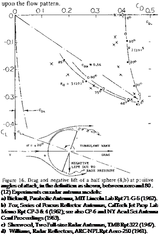
Half Sphere. When reversing the direction of flow against a “cap” we obtain the flow pattern around a half sphere, as in figure 16. Drag and lift coefficients are plotted in polar form. The lift-curve slope is negative; between (+ and —) 10 (in the definition as shown) it is found:
dCLe/dcy° =-0.01 (8)
 Lift also remains negative up to angles above 85* The moment around oc = 0°, about the center of the sphere, is given by
dCmd/d</ =-0.0007 dCmd/dCL =+0.700
Lift and moment are thus “unstable”. Drag may correspond to CD = 0.4, plus Cp; = C^/trA = C /4. For practical purposes CD =0.4 for ex’ between (+ and —) 20c.. The open cup (hollow half sphere) also plotted in figure 16 shows somewhat different coefficients, in particular less drag at of between + 20 and —20°. Besides the open base (bottom) the Reynolds numbers is likely to have an effect
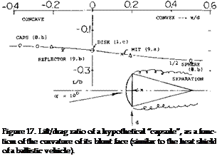
Gliding. Satellite capsules such as those developed in the United States (7) can al so be steered when re-entering, in longitudinal and/or lateral direction, by means of the high pressure forces on their blunt heat shield. This happens at supersonic speeds; the principle is the same, however, as in figure 15,b. Some kind of diving capsule could also be designed to be used in deep water. The gliding angle could be controlled either by shifting a weight inside, or by adjusting the angle of attack (against the water with the help of a flap, for example). Some (L/D) values are plotted in figure 17. This value is approximately proportional to the angle of attack as against the body axis. There would be a limiting angle, however, where the flow gets attached to one side of the afterbody assumed to be conical. It should also be noted that with the CG behind or above the blunt front end, vehicles of this type are likely to be stable.
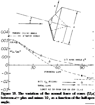
Cones. In a manner similar to the lift of the wedges in figure 10 the normal-force derivative of cones (with their point against the wind) reduces as the cone angle is increased. The experimental data plotted in figure 18 have been extended. For small cone angles, equation (3) in (12,b) can be applied. At t = 90 , we have a thin disk as in (7,e). Its force normal to the axis is zero. The center of forebody pressure is roughly obtained as indicated in the sketch. It moves from x/d = 0.97 (ahead of the base) for £ = 10°, to —0.47 (behind the base) fort = 50°. In reality, the cones also have a negative base pressure, contributing to drag, and providing a negative component of lift (at right angle to the direction of the wind) similar to that in figure 10 at larger angles.
Rotating Spheres. The motion of spinning tennis, golf and base balls show that lateral forces are developed that cause them to curve in flight. For instance, it has been shown (14,b) that a regulation baseball as used in the National or American Legues which weighs between 5 and 5lA ounces and is 9 to 9lA inches in circumference will move as shown
|
speed |
V |
= 100 ft/sec |
|
spin |
n |
= 1200 rpm |
|
distance |
X |
= 60 ft |
|
“curve” |
У |
= 1 foot |
![]() The spin of 1200 rpm means a speed ratio of w/V = 0,15. The speed corresponds to a Reynolds number based on diameter of Rj = 5.7(10)b which would result in a Row pattern above the critical.
The spin of 1200 rpm means a speed ratio of w/V = 0,15. The speed corresponds to a Reynolds number based on diameter of Rj = 5.7(10)b which would result in a Row pattern above the critical.
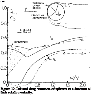
Test data (14,a, c) on the lift and drag coefficients measured on smooth rotating spheres is given on figure 19. These data essentially confirm the results-given in “Fluid Dynamic Drag” and show a CLx of between 0.4 and 0.45.
As in the case of a rotating cylinder, the lift and drag coefficiens are dependent on the rotational speed ratio w/V. This ratio is important as it effects the separation on the cylinder and thus the lift. Since the lift is dependent on the separation points on the upper and lower surfaces it would be expected that surface roughness and Reynolds number would effect the results. Qualitative data is not available for an evaluation.
Normally when considering the forces acting on ground vehicles the drag force is of primary concern, as this effects the power required. The variation of the drag force of representative vehicles with variations of shape are covered in “Fluid-Dynamic Drag” and (15,a). The lift forces produced by a vehicle can be important, especially if we consider the side force to be lifted as in the case of a vehicle operating in a cross wind. In this case, the side force will effect the stability and handling characteristics of the vehicle.
(13) Lifting characteristics of cones moving point-first:
a) Owens, Large of Cones M = 0.5 to 5.0, NASA TN D-3088 (1965).
b) See results in the “wing and body” chapter.
(14) Lateral forces on revlolving spheres:
a) See “Drag Due to Lift” in Chapter VII of “Fluid-Dynamic Drag”.
b) Briggs, Deflection (curve) of a Baseball, NBS Rpts 1945 and later, NY Times “Sports” 29 Mar 1959.
c) Niccum, Lift and Drag of a Rotating Sphere, Dept of Aero & Mech, U of Minn. 1964.
Automobile Lift. The lift coefficient of the conventional passenger car is given on figure 20 as a function of angle of attack. Here, the lift force, L, is that tending to decrease the weight of the vehicle on the road
Cu=WqSf (10)
where Sf is frontal area of the car.
Even at an angle of attack of zero automobiles have a positive lift coefficient of 0.3. This is due to their basic shape, which is effectively cambered. The lift curve slope is high and shows the importance of ground effect. Although the lift coefficients for the automobile are high, the actual lift is very small in comparison with the weight of the basic car. For instance, even at 90 MPH and a lift coefficient of 1.0 the actual lift force is only of the order of the weight of one passenger. This is small considering automobiles in the 3 to 4Q00 weight class.
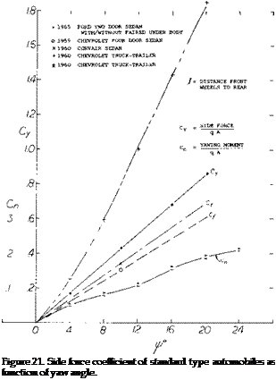
The more important lift force on an automobile is that produced in a cross wind. Although the side force coefficient is the same order of magnitude as the lift force, figure 21, it is more significant as it will effect the directional control of the car. It should also be noted that the actual lift coefficient of the car increases with yaw angle. An increase up to 0.5 due to a yaw of 25° (15,c). The importance of the side force is due to the variation of the force due to sudden changes. For instance, when operating a light weight car or trailer in a cross wind, the passing of a large truck can cause a sudden side force change of 50 to 200 pounds. This can cause sudden unwanted direction change, which can be dangerous. Thus, automobile shapes which minimize the side force are desirable. The large side force produced by trucks causes a side-wash change in the direction of the air, which is also a safety problem.
(15) Ground vehicles lift and side force:
a) Turner, Automobile Test Moving-belt, NASA TN-D-4229.
b) Flynn, Truck Aerodynamics, SAE Preprint 284A, 1961.
c) 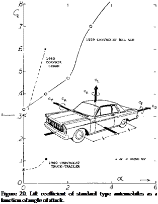
 Whitcomb, Aero Forces on Critical Speed of Automobiles, CAL Report No. YM-2262-F-1 (1966).


