Control derivatives
The controls influencing the lateral and directional motion of the helicopter are assumed to be only lateral cyclic pitch and tail rotor collective pitch. Although movement of the collective lever changes torque and hence the tail rotor thrust required for trim, this will not be considered in our discussion so collective may be assumed effectively constant during lateral control inputs. The derivatives are denoted
by LAl, -4, , N, u.
4.11.2 Lateral/directional motion of the helicopter
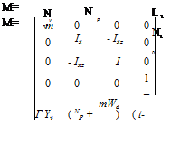
Details of the general equations governing lateral and directional motion are given earlier. It is common practice for lateral/directional motion to assume that all acceleration dependent derivatives are negligible and that the centre of gravity is on the main rotor drive shaft such that dx = dy = dz = 0. Thus:
Mm x = Ma x + Mc u
 |
where:
|
v" |
” v" |
"YAl |
V |
||||
|
p |
p |
^l |
Mc = |
L Al |
L 0tr |
||
|
x= |
u= |
||||||
|
v |
r |
_0tr _ |
NAl |
N0tr |
|||
|
_Ф_ |
_Ф_ |
0 |
0 |
To proceed further it is necessary to convert the matrix equation into the form:
x = Ax + Bu
This is achieved by pre-multiplying Mm, Ma and Mc by the inverse of Mm, (M). Noting that r = tjz and including the effect of ^ on lateral acceleration:
|
1 m |
0 |
0 |
0 |
0 |
|
0 |
Izz |
Ixz |
0 |
0 |
|
(Ixx Iz -12z) |
(Ixx Izz -12z) |
|||
|
0 |
Ixz |
Ixx |
0 |
0 |
|
(Ixx Izz -12z) |
(IxxIzz -12z) |
|||
|
0 |
0 |
0 |
1 |
0 |
|
0 |
0 |
0 |
0 |
1 |
|
M“i = |
Hence:
|
~Yv |
(Yp + We) |
(Yr – U) |
g cos ee |
g sin ee |
~ya, |
Yet~ |
|
|
Lv |
LP |
L’ |
0 |
0 |
La, |
Letr |
|
|
Iv |
NP |
I’ |
0 |
0 |
B = |
yn, |
Ie etr |
|
0 |
1 |
0 |
0 |
0 |
0 |
0 |
|
|
0 |
0 |
1 |
0 |
0 |
0 |
0 |
|
A = |
 |
where:
|
s — Yv |
1 1 |
Ue — Yr |
— g cos ee |
g sin e |
|
|
— Lv |
s — Lp |
— Lr |
0 |
0 |
|
|
CE = |
— Nv |
— N |
s — Nr |
0 |
0 |
|
0 |
—1 |
0 |
s |
0 |
|
|
0 |
0 |
—1 |
0 |
s |
Thus for lateral/directional motion, As5 + Bs4 + Cs3 + Ds2 + Es = 0, which usually becomes:
(T s + 1)(T2 s + 1)(s2 + 2^mn s + m2 )s = 0
The four modes of motion are summarized below:
(1) Heading mode. The heading mode is represented by the root s = 0 that indicates that the aircraft has neutral yaw angle stability.
(2) Yawing mode. The yawing mode, which is equivalent to the fixed wing, spiral mode, is represented by (T1s +1) = 0. The mode is independent of roll and lateral translation and is an exponential motion that can be either convergent or divergent. The time constant is moderately long being typically between 5 and 20 seconds.
(3) Rolling mode. The roll mode, described by (T2s + 1) = 0, is a damped subsidence in pure roll. The motion has a short time constant of the order of 1 to 2 seconds.
(4) Lateral/directional oscillation. The Lateral/Directional Oscillation (LDO) or Dutch roll, is an oscillation in roll and yaw, which like the pitching oscillation can be flight condition dependent. Typically the oscillation is unstable in the hover and in a climb.


