Evaluating control forces
Measuring the force gradient for a control is achieved using either a spring balance or a force gauge placed at the relevant CR Point. The force is applied in a slowly increasing manner to note the precise force at which the control starts to move; this will give the value of the breakout force plus the static friction (B + F). Having overcome B + F, the standard convention is then to use only sufficient force to keep the control moving. The force required is recorded at regular intervals of displacement
|
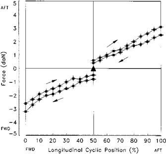
Fig. 5.2 Force/displacement plot: longitudinal cyclic stick. |
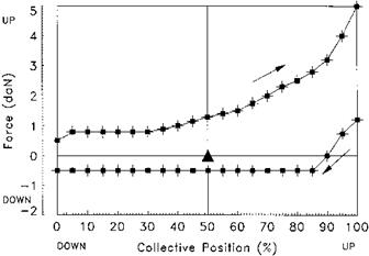
to allow the production of a force/displacement plot as shown in Fig. 5.2. When the limit of displacement has been reached the force is reduced gradually until the control moves back towards the trim point. Note on Fig. 5.2 that having reached full displacement the control will not start to move back towards the trim position until the force has been reduced by a value equal to twice the static friction. If a control friction device is fitted it is usually placed in the fully OFF position when measuring the forces. If there is no trim system then it is still necessary to measure and document the value of the sliding friction. An example of a collective force/displacement plot is shown in Fig. 5.3. Pilots are very sensitive to the value of B + F as the majority of control inputs are small being used to make minor adjustments to the helicopter’s flight path. If B + F is set too high it will make precise control difficult and some pilots deliberately fly holding a trim force during tasks such as instrument approaches to overcome this problem. On the other hand too weak a force will lead to inadvertent small control inputs due to vibration or turbulence. Where an adjustable friction device is fitted this is assessed to determine if it can be used to set precise amounts of friction. For obvious reasons it should not be possible to lock the control by setting excess friction.
The designer of the control system will set the value of the cyclic force gradient to allow the pilot to move the control rapidly, but at the same time sufficient force gradient must be provided to prevent unintentionally large inputs. In the case of aircraft with high cyclic control power the need to provide protection may predominate and the force gradient may be quite high. This will have a significant effect on handling qualities during manoeuvres where the control has to be moved faster than can be achieved with a beeper trim system, or where trimming is not desirable, such as during a flyaway from the hover following a single engine failure. In this case the need to
|
Fig. 5.3 Force/displacement plot: collective lever. |
overcome a high spring feel force will make the flyaway more difficult to achieve and may cause an excessive height loss. On the other hand too shallow a force gradient will also lead to problems with the pilot making excessively rapid inputs; the pilot may then feel constrained into making only gentle inputs to avoid this problem and thus may not achieve the full agility of the helicopter. It is also necessary to assess the maximum force that a beeper trim system can produce, known as the limit control force, to determine if the pilot could retain control with a trim runaway. Holding the control at one end of its available range and then trimming fully in the opposite direction stimulates this.
Where a force trim release button is fitted the sudden release of the force will often cause the control to ‘jump’ as the pilot changes the amount of force he is applying. In the case of the cyclic this is known as stick jump. To the pilot this can become irritating, as it is not possible to make small changes to the datum trim position. To test control jump, the control is displaced from the trim position, the release operated and the reaction of the control noted. The amount of displacement used for this test is a realistic amount that an operational pilot might employ before operating the release. After ground tests, an airborne assessment is made to determine if any control oscillations cause an undesirable aircraft response.
Associated with the force gradient tests are the determination of the centring characteristics. This is the tendency of the cyclic to return towards the trim point when any displacing force is removed. Positive centring indicates a return towards the trim point while absolute centring is achieved if the control returns precisely to the original trim position. When conducting this test the control is displaced from trim and then allowed to return slowly towards trim. Where centring is positive but not absolute there will be a trim control displacement band (TCDB). This occurs as a consequence of a weak breakout force that is insufficient to overcome sliding friction. If the cyclic is moved to any position within this band and released it will stay at that position.
The implications of a trim control displacement band will vary according to the flight task and will not always have a detrimental effect on aircraft control. For example, when instrument flying a large TCDB would make it difficult to control aircraft attitude but a small band would allow the pilot to make small attitude changes without having to re-trim. A small TCDB may also make hovering easier again by obviating the need to make constant trim inputs. It is important, however, to understand that a TCDB will have implications for AFCS functions which use cyclic position as an input. For example, an attitude command/attitude hold system would not return the aircraft to the original attitude after a pilot input if a TCDB was present. The TCDB can be reduced by reducing the amount of friction in the system or by increasing breakout force.
It should be remembered that force gradients are not always linear and sometimes soft stops are incorporated such as the intermediate and maximum pitch stops in the Aerospatiale AS 341 Gazelle collective control. These soft stops can be incorporated for a number of reasons such as cueing the pilot to the limit of the power-on collective lever movement or defining the surge-free range of lever displacement. The cueing properties of the stop and the force required to overcome it are assessed during manoeuvres that require large and rapid control movements. For example, if the force required to overcome a stop is too high it might have serious implications during an engine-off landing if it interfered with the application of collective pitch at touchdown.
Since harmonization of control forces is an important aspect that will affect the aircraft’s handling qualities, the force gradient in any axis should be matched with the breakout force. For instance, if there is a high breakout force and a shallow force gradient it will be difficult to make precise inputs which require the control to be moved through the trim point. This may make manoeuvres such as hovering and NOE flight difficult. Harmonization of the forces of all the flight controls and between the lateral and longitudinal axes of the cyclic is also important for good control. It is the pilot’s perception of harmony between the forces that is the important issue not necessarily the actual values. This is due to the physiology of the human body that makes it easier to generate higher forces with the legs than with the arms; similarly it is easier to push the cyclic to the left than pull it to the right. Specifications such as ADS-33E [5.2] encompass this idea of ‘perceived’ or ‘apparent’ harmony by merely stating that forces, displacements, and sensitivities… shall be compatible’, without specifying values. Where the control forces are poorly harmonized manoeuvring is more difficult particularly during manoeuvres that require extensive use of all controls such as pirouettes [5.2] or downwind quickstops.


