Flapping motion due to steady pitch or roll rate
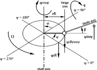
The application of a steady pitch or roll rate (see Fig. 4.9) to a rotor system is an important scenario since it introduces not only the concept of rate cross-coupling but highlights the existence of aerodynamic damping resulting from the interaction between the main rotor and the fuselage. The following discussion will consider only the flapping motion due to a pitch rate; the situation when a steady roll rate is applied can be tackled in an analogous manner. The analysis begins by returning to the basic flapping equation (4.19):
Iyy m2 – Iyy m1 m3 – mbXgRaz = M
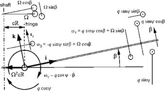
From Fig. 4.10, it can be seen that:
m1 = q sin ^ cos p + ) sin p t
m2 = q cos ^ — p > (4.26)
m3 = — q sin ^ sin p + ) cos P J
Therefore for a constant pitch rate:
m 2 = q cos ^ — qvjr sin^ — p = q cos ^ — q) sin ^ —p = —q) sin ^ —p (4.27)
|
|
|
In addition, using small angle approximations and assuming q2 is small compared with )2;
![]() m3 m1 = (— q sin ^ sinp + ) cos P)(q sin ^ cos p + ) sin p) m3m1 = — q2 sin2 ^p — q) sin ^p2 + q) sin ^ + )2p = q) sin ^ + )2p
m3 m1 = (— q sin ^ sinp + ) cos P)(q sin ^ cos p + ) sin p) m3m1 = — q2 sin2 ^p — q) sin ^p2 + q) sin ^ + )2p = q) sin ^ + )2p
Thus substituting Equations (4.27) and (4.28) into Equation (4.9):
Iyy m 2 — Iyy m1 m2 — mb Xg Raz = M — Iyyp — Iyy q) sin ^ — Iyy q ) sin ^ — Iyy )2p — mb Xg Raz = M
mb Xg Raz MA
![]() УУ
УУ
Now the vertical velocity of the hinge as a consequence of the pitch rate can be seen from Fig. 4.11 to equal:
![]()
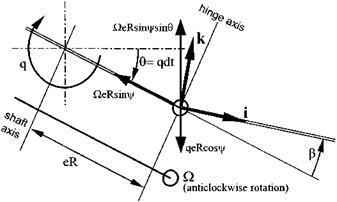 |
V = )eR sin ^ sin 0 — qeR cos ^ = )eR sin ^0 — qeR cos ^
Therefore the vertical acceleration, again as a consequence of the pitch rate, will be:
Substitution for the angular velocity components of the blade and the acceleration of the hinge given by Equations (4.11) and (4.30), leads to:
P + )2(1 + s)P = )2 d^ + )2(1 + s)P = – 2)q(1 + s) sin У (4.31)
Uy – lyy
Due to the combination of pitching and flapping, the change in blade incidence at a point r from the flapping hinge is given, for small flap angles, by:
* _ rm2 rq cos У — rp
“ = )(r + eR) = )(r + eR)
Therefore as before:
![]()
SL = 2 p V2sCL =1 p)2(r + eR)2cr Sr a
and:
= 2 pac)(q cos У — p)R4(1 — e)3(1 + e/3)
So:
![]() M у.
M у.
—— = у )(q cos У — P)(1 — e)3(1 + e/3) = n)(q cos У — p)
lyy 8
and on substitution of Equation (4.32) into Equation (4.31):
Once again only the steady state result is of interest. Thus if: P = a0 — a1 cos У + by sin У then the solution to Equation (4.33) is given by: qn(3s + 2)
)(S2 + Щ2 )
![]() q[2s(s + 1) — щ2]
q[2s(s + 1) — щ2]
)(s2 + n2)
n = 8(1 — e)3(1 + e/3)
Consider the case when the hinge offset is zero, e = s = 0, so:
![]() a1 =
a1 =
Hence for a steady nose-up body pitch rate the rotor develops a nose-down tilt relative to the fuselage. The tilt is proportional to the pitch rate and is inversely proportional to Lock number. A moment is therefore generated via a forward tilt of the thrust vector that opposes the original nose-up moment. Thus the rotor develops aerodynamic damping which in the longitudinal sense will contribute, along with the tailplane, to the magnitude of Mq. Note also that a body pitch gives rise to lateral flapping such that a nose-up pitch produces a disk tilt to port. Hence rate cross-coupling occurs even when the hinge offset is zero, unlike with acceleration cross-coupling. It can be shown that for a uniform blade:
a,) 4y(l – e)4(l + e/3) (5e + 4)
~q~ = [144e2 + y2(1 – e)8(1 + e/3)2]
and
96e(2 + e) – y2(1 – e)8(1 + e/3)2
4y(1 – e)4(1 + e /7) (5e + 4)
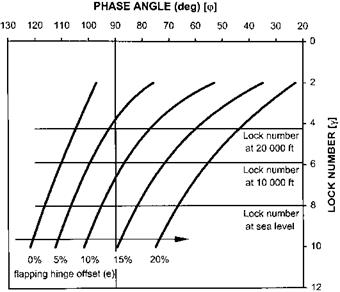
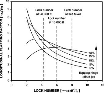
The variation of aerodynamic damping (proportional to a,)/q) and rate crosscoupling with hinge offset and Lock number are presented in Figs 4.12 and 4.13 respectively. Figure 4.12 indicates that at high Lock number the level of aerodynamic damping increases with hinge offset. Figure 4.13 shows that the tendency for the disk
![]()
|
Fig. 4.13 Example of rate cross-coupling. |
to tilt to port with a nose-up pitch rate changes with both Lock number and hinge offset. Recalling that Lock number is air density dependent allows an estimation of the variation of damping and cross-coupling with altitude. If a Lock number of 8 at sea level is assumed then it can be seen that at high altitude the aerodynamic damping will be greater for a rotor of modest hinge offset and the tendency of the aircraft to roll to the left may be replaced by a tendency to roll right, especially at high values of hinge offset. The increase in rotor damping with altitude may appear a little confusing but it should be remembered that the damping arises from the interplay between the tilt of the rotor due to aerodynamic forces and the inertia of rotor due to gyroscopic effects. Hence at high altitude the inertia forces will be stronger and the rotor will have a greater tendency to retain its position in space whilst the fuselage pitches nose up, thereby resulting in a greater relative nose-down disk tilt. Note that the increased off – axis response of a rotor with a high hinge offset at high altitude causes a reduction in aerodynamic damping.


