Polar Equations
The derivation of the polar equations is more complicated. We have to transfer the rotational derivative of Newton’s equation first to the Earth frame and then to the reference frame associated with the geographic velocity. Only then have we created the intuitive format we desire.
The point of departure is again Eq. (8.1). First, we deal with Newton’s acceleration afs = DlvlB and transform the rotational derivative to the frame E:
DrvB = DEvB + Г2 EIvIB
Then we substitute Eq. (8.3) into both terms on the right-hand side:
DlvlB = Dev f + DE(nElsBi) + SlEIvEB + nEInEIsBi (8.8)
Apply the chain rule, realizing that Earth’s angular velocity is constant
DE(nEIsBi) = DEnE, sB, + nEIDEsB, = nE, DESBi
and expand the term further by the vector triangle sBi = Sbe + s ei, making use of the facts that Sei = 0 and that the geographic velocity is defined by v § = DesBe’-
Ue, Desbi = nEr(DEsBE + DesEi) = nElDEsBE = nElvE
Substituting into Eq. (8.8) and collecting terms yields
D’v’B = Deveb + mEIvEB + nEInEIsBi
Now we introduce the velocity frame V, which is defined by its three base vectors V], V2, V3.The direction of the geographic velocity vector vf defines Vi, while v 2 is normal to it and horizontal and V3 completes the triad. Transforming the rotational derivative DEvB to the V frame yields the final form of the inertial acceleration:
D’vB = Dvv I + + inEIvEB + nEInEIsBi
We are ready now to replace the rotational derivative in Newton’s law and thus obtain the translational equation of motion
DvvEB+nVEvE = -fap+g – mEIvE – nEInEIsBI (8.9)
m
It contains the famous Coriolis 2EIeivb and centrifugal EIeiEIeiSbi accelerations, which we encountered already in Sec. 5.3.1. Another integration yields the position Sbi of the missile c. m. В wrt the center of Earth / (recall that points / and E coincide):
DEsBi = vE (8.10)
These are six coupled differential equations. As intended, the missile’s acceleration is referred to the velocity frame. This shift in reference frame introduced the angular velocity u>VE of the velocity frame wrt Earth.
For a nonrotating Earth the equations are uncoupled and reduce to the flat-Earth three-DoF model
Dvveb + Uveve = ±fap+g
DesBe = vf
where Earth’s reference point E can be any fixed point on Earth.
Equations (8.9) and (8.10) are valid in any coordinate system. We pick the flight – path coordinates for ease of expressing the geographic velocity vector simply as
[^|]V = [V 0 0]; V = |vf I
However, Earth’s angular velocity and the vehicle’s position are best expressed in Earth coordinates and the gravity vector in geographic coordinates:
![]() + [QVE]V[VEB]V = -[fa, p]V + [T]VG[gf
+ [QVE]V[VEB]V = -[fa, p]V + [T]VG[gf
L J m
– 2[T]VE[£lEI]E[T]ve[veb]V – [Г]У£[^£/]£[^£/]£[^/]£ (8.11)
![]() = [t]VE[vEB}V (8.12)
= [t]VE[vEB}V (8.12)
Some of these terms have simple components:
![]() = [V 0 0], [g]G = [0 Ogravdswl)], [o)£/]£ = [0 0 coEI]
= [V 0 0], [g]G = [0 Ogravdswl)], [o)£/]£ = [0 0 coEI]
The transformation matrices that need to be programmed are [ T VG from Eq. (3.25) and [T]VE = [T]VG[T]GE with [T]GE from Eqs. (3.13).
 |
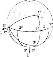
The angular velocity u>VE of the velocity wrt the Earth frame needs special attention. We derive its component form [ooVE~v from Fig. 8.1. It consists of the
vector addition of the angular rates x and у times their respective unit vectors Xj and v2:
VF. , .
<*> = Х*з + yv2
Coordinated
[wVE]v = Х[Т]УХШХ + ylv2Ґ
and expressed in component form
|
cos у |
0 |
—sin у ~ |
‘O’ |
"O’ |
■ – x sin у – |
||
|
0 |
1 |
0 |
0 |
+ Y |
1 |
— |
Y |
|
.sin у |
0 |
cos y_ |
l |
0 |
xcosy. |
|
The left side of Eq. (8.11) becomes then
V |
X V cos у
-Vy
with the three state variables: speed V, heading rate x, and flight-path rate y.
The flat-Earth implementation again is easier to program because the last two terms of Eq. (8.11) vanish and the local-level axes ]L replace the geographic and Earth coordinates
 -[fa, P]V +lT]VL[g]L (8.13)
г
L
= mVL[vEBY (8.14)
Comparison of Eq. (8.11) with Eq. (8.4) clearly shows the greater complexity of the polar formulation. However, the three state variables V, x, and у are easier to visualize than the inertial velocity components [Ug]7. Under the flat-Earth assumption, both the polar equations (8.13) and (8.14) and the Cartesian equations (8.6) and (8.7) are programmed with the same ease. Equation (8.13) actually has the advantage that the angles for the TM 1T]VL are computed directly.
You may have been deafened by my silence over the right-hand side of Newton’s law. The impressed forces consist of surface forces (aerodynamic and propulsive) and volume forces (gravity). Dividing the surface forces by the vehicle’s mass generates what is called the specific force, but actually it is an acceleration. Accelerometers of INS measure this specific force. They cannot sense the gravitational volume force. In the following sections I delve deeper into the modeling of aerodynamic propulsive and gravitational forces.


