Stability and Control Testing
5.1 ASSESSING FLIGHT CONTROL MECHANICAL CHARACTERISTICS
When evaluating control aspects of rotorcraft the first aspect to consider is the characteristics of the control system. As the pilot must control the swashplate through the flight controls a deficiency in their operation will affect all areas of flight. Even excellent aircraft handling qualities can be masked by poor flight control mechanical characteristics (FCMC). Testing can be divided into quantitative aspects which normally take place on the ground and qualitative aspects which are conducted in flight. As quantitative testing is concerned with the measurement of forces and displacements it can be conducted more easily and safely on the ground. For reversible systems, however, the amount of ground testing that can be undertaken is limited by the requirement to have the rotors turning and by the need to evaluate realistic flight forces. Qualitative testing is concerned with the effect that the control system characteristics have on the conduct of role tasks. This section will only cover conventional control systems with displacement controllers.
In any assessment that includes FCMC a comprehensive control reference system is defined. This establishes the test conditions in case the controls of an aircraft are modified at some stage subsequent to the assessment. The reference system records the range of movement for all the controls. As the distances through which controls move and the forces needed to move them vary depending on where the measurement is made, it is necessary to define this point which is termed the control reference point (CR Point). The definition is usually given in specification documents such as the Ministry of Defence Standard 00-970 [5.1]. Having defined the CR Point for each control the next stage is to determine a position within the throw of each control from which displacements are measured. The position is known as the control reference position (CR Posn). The CR Posn can be defined anywhere along the control throw although it is usual to set the position at the mid-point for the cyclic axes and the yaw pedals. The convention for the collective is to use the minimum pitch position. By measuring the distance to the cyclic CR Posn from three points on the aircraft structure it is possible to reference the control envelope to the cockpit as a whole. As the pedals and collective only move in one direction, or follow an arc, a single measurement normally suffices to define the location of the CR Posns for these types of controllers.
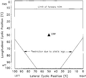
The cyclic control envelope is the area described by the maximum cyclic displacement (measured at the CR Point) in all directions. The envelope can only be measured fully with rotors stopped. Of course the assessment of the acceptability of the envelope can only be made in flight. Determining if the control envelope is satisfactory is not as simple as it may seem at first. If items within the cockpit restrict the range of control
|
Fig. 5.1 Cyclic stick displacement envelope. |
movement it is not necessarily a deficiency; it is only significant if the restriction is encountered during flight manoeuvres. Of course it is important that the pilot is able to reach the required envelope of all the controls from the normal seated position. A typical presentation of a cyclic envelope is shown in Fig. 5.1. The envelope may be affected by the operation of mechanical interlinks and is measured with the collective and yaw pedals at both ends of their displacement range. The position of the pilot’s seat can affect the amount of the envelope that can be used and this is placed in the most restrictive position – fully forward and normally fully up. Where the displacement that can be achieved using the trim system is less than the full displacement then this too is presented on the envelope plot. Problems are sometimes experienced with the envelopes of the other controls; for example, to lower the collective lever fully some pilots have to lean over to an uncomfortable degree. This highlights the importance of recording the assessing pilot’s anthropometric data and seating position.


