Variation of control power with hinge offset
It has already been shown that a flapping hinge offset results in an increase in aerodynamic damping. Flight experience suggests that rotors with large hinge offsets also have a high degree of control sensitivity. In other words such a rotor causes a rapid acceleration in pitch and roll which combined with the high damping gives short time constants. Thus a rotor with a large hinge offset will display a crisper control response than one with a small offset; a steady pitch or roll rate being achieved rapidly after the application of step control input. The reason for this differing response lies in the fact that the hinge offset itself gives rise to additional forces and moments that
|
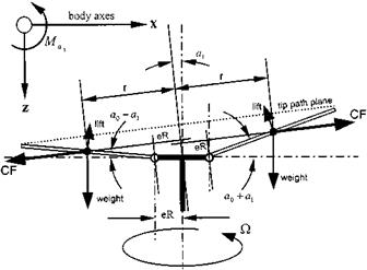
Fig. 4.14 Offset flapping hinges. |
accelerate the aircraft in pitch or roll. From Fig. 4.14 it can be seen that as the blade flaps the lines of action of the centrifugal forces are no longer coincident; thus a couple is produced. This couple produces a moment at the hub that reinforces the disk tilt demanded by pilot control input: nose-up disk tilt produces a nose-up hub moment.
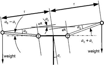
The hub moment arises from the separation between the lines of action of the centrifugal loads on opposite blades. In the longitudinal sense the separation is a function of the magnitude of a1. Thus from Fig. 4.15 the maximum moment per blade is:
M = 2CFeR tan a1 (4.34)
|
|
Now:
CF = mb r() cos a1 )2
where r is the radial location of the centre of mass from the axis of rotation.
For a blade with a uniform mass distribution:
CF = mbieR + 2(1 — e)Rcos a0 j)2 cos2 a1 (4.35)
Hence using Equations (4.34) and (4.35):
 M = eRmbieR + 2(1 — e)R cos a0
Assuming a small coning angle and disk tilt; tan a1 = a1 and cos a0 = cos a1 = 1:
M = eR2mb (1 + e) )2a1
The average longitudinal moment is obtained by noting that the moment varies from the maximum value given above to zero. Thus since the longitudinal moment will only arise from longitudinal flapping and for b blades:
be
M = y(1 + e)mbR2 )2a1 (4.36)
Now the control power is defined as the moment generated for maximum control deflection, thus from Equation (4.36):
Mai = dM = 2 ebR2mb (1 + e) )2
Hence the larger the hinge offset the larger the additional moment. Thus it is now possible to describe the control response of a rotor with a hinge offset. When compared with a teetering rotor, a rotor with a significant hinge offset will display a larger control sensitivity since the additional moment described above will reinforce the moment achieved by tilting the thrust vector so giving a greater angular acceleration. The higher aerodynamic damping associated with hinge offset then causes the acceleration to decay rapidly. Thus the time to steady pitch or roll rate is inversely proportional to the size of flapping hinge offset, see Figs 4.16 and 17.


