Altitude hold autopilot
There is little difference between a five – and six-DoF altitude hold autopilot. Two feedback loops are wrapped around the acceleration autopilot (see Fig. 9.18) with two gains G# and Gy determining the dynamic response. To prevent large error signals driving the acceleration loop, I inserted an altitude rate limiter HDTLIM. The measured signals are altitude rate from the INS and altitude from an altimeter. According to our pseudo-five-DoF approach, the acceleration autopilot provides the angle of attack that is needed in the aerodynamic table look-up routines. The airframe block provides the remaining dynamics and measurements.
Let us address the need for the gravity bias term. When the vehicle flies straight and level, the altitude error signal is zero. However, to counteract gravity the airframe must generate a 1 – g load factor. This commanded input is provided by the gravity bias term.
We have to distinguish between the implementations for skid-to-tum and bank – to-turn vehicle. While the altitude controller operates in the vertical plane, the
НПТІ. Ш Gravity bias
![]()
![]() a
a
I____ Altitude rate feedback
Altitude feeback_____________________________________
 |
Fig. 9.19 Altitude hold autopilot for bank-to-turn and skid-to-turn vehicles.
pitch plane of the vehicle can be banked through the angle фву – The adjustments through cos фву are shown in Fig. 9.19, as well as the two integrations that convert the vertical acceleration ay into altitude rate and altitude. If фву = 0, the vehicle executes skid-to-turn maneuvers and cos фву = 1 ■
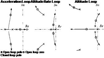
To determine the gains G# and Gy, we start first with the design of the acceleration autopilot followed by a root locus analysis of the inner and outer altitude loops. Figure 9.20 shows the root locus patterns. The complete altitude hold loop has five closed-loop poles with a dominant oscillatory complex conjugate pair. For the CRUISE5 concept I selected the constant values
Gh = 0.5, Gv = 1, HDTLIM = 20 m/s
They give good performance also for terrain following and obstacle avoidance flights.
 |
We will stop here. You may require other autopilot functions for your specific vehicles, but I hope that these three examples, illustrating the idiosyncrasy of pseudo-five-DoF simulations, will enable you to devise your own designs. On the CAD AC CD you will find several other options like flight-path-angle hold, thrust vector pointing for reentry vehicles, yaw and pitch rate hold, etc. Look up the FORTRAN code and see if any one suits your applications.


