Computer generated sweeps
Some test agencies advocate the use of automatic input devices that can generate ‘pure’ sinusoidal frequency sweeps by injecting inputs directly into the pitch change linkage actuators. This method generally makes analysis easier and gives a degree of repeatability. However since the input and response will be subject to spectral analysis, the exact shape and size of input is not critical. Indeed, the analysis of an ‘imperfect’ frequency sweep may yield information on frequencies higher than the nominal maximum due to discontinuities in the input. Additionally, computer generated sweeps do not account for the effects caused by the mechanical flying controls and the man – machine interface such as biomechanical feedback caused by vibration through the pilot’s limbs. It is vital that such effects are identified so that appropriate ‘notch’ filters can be included in the flight control circuit if necessary. Additionally, sweep data that has not been generated by a pilot is rarely acceptable for handling qualities studies or demonstration of compliance. Finally, a pilot is able to adapt his control inputs in an intelligent way to account for drift from the trim condition.
5.6.1 Data analysis and specification compliance
Having described a suitable method for gathering frequency response data in-flight, precisely how such information is used for checking specification compliance now
|
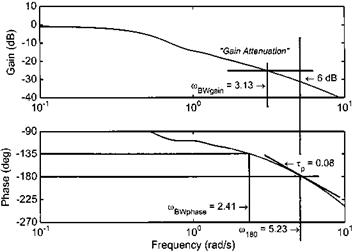
needs to be considered. Since most of the requirements concern the manner in which phase lag varies with frequency, a start will be made there. Typical of all helicopters is the tendency for the output (aircraft attitude) to lag the input (control deflection) by larger amounts as the input frequency is increased. The requirement on the pilot to apply larger amounts of lead to overcome this increasing phase lag, or shift, leads to an increase in workload. Ultimately at high input frequencies, the aircraft response will reach 180° out of phase (m180) and will be neutrally stable [5.4] with control deflections required in the same direction as any disturbances in order to counter them. Although it is possible in such circumstances for an experienced pilot to maintain control, there will almost certainly be excessive workload that will undoubtedly prejudice mission effectiveness. For adequate handling qualities, it is necessary to avoid this situation by ensuring that the bandwidth of the aircraft exceeds that required for the mission. When gathering data for frequency response analysis, as indicated above, the rotorcraft is essentially operated in an open-loop manner that is quite different to the closed-loop nature of all high-gain mission tasks. The definition of phase-limited bandwidth considers this fact by specifying a 45° phase margin that allows for the neuro-muscular lag associated with a pilot operating with full attention but less than maximum effort [5.5]. Thus, the phase-limited bandwidth (fflBWphase) is simply defined as the frequency at which the phase lag reaches 135° (2.41 rad/s in Fig. 5.24).
In researching the use of bandwidth as a general criterion, it was discovered that pilots were also sensitive to the rate at which phase changed in the region of the bandwidth frequency and the point of neutral stability. Commensurate with the simple definition of bandwidth the phase rate, or phase delay, uses a two-point approximation of the phase curve between m180 and 2m180, thereby assuming a linear roll-off in phase throughout this critical region. Thus from Fig. 5.24:
|
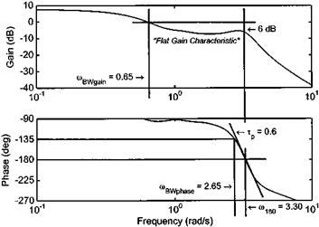
Fig. 5.25 Frequency response of a gain limited system. |
When operating unaugmented helicopters or ones fitted with a rate command system, pilot inputs are required to provide attitude maintenance, especially in gusty conditions. This is different to attitude command/attitude hold (ACAH) systems, where the pilot can reduce his own personal gain and rely on the inherent attitudekeeping features of the rotorcraft. Consequently, research using rate or rate command/ attitude hold (RCAH) response types highlighted the need for a further definition of bandwidth as it was found that the variation in gain with frequency had a significant impact on the handling qualities ratings awarded [5.5]. Handling problems were found when pilots attempted to operate helicopters with high phase delay and flat gain characteristics in the region of the phase limited bandwidth. When required to fly more aggressively or with greater precision, pilots have a natural tendency to increase both the size and frequency of their inputs as they attempt to ‘tighten’ control of the helicopter. This tendency is more evident if the phase delay is large since the helicopter will suddenly appear to be ‘getting away’ from the pilot as the bandwidth frequency is approached. A further complication arises if the gain characteristics are flat rather than being attenuated. With gain attenuation, the tendency of the pilot to increase input magnitude is mitigated by a reducing output/input ratio, see Fig. 5.24. However, if the gain characteristic is flat then as the pilot makes larger inputs he gets an unchanged or even a larger output which coupled with a large phase lag can result in PIO, see Fig. 5.25.
The concept of gain-limited bandwidth (fflBWgain) was developed as a means of avoiding this problem. Since pilots can act as amplifiers and are capable of doubling their gain, mBWgain is determined by applying a gain margin of 6 dB (20log10 (2) = 6) to the open loop data as shown in Figs 5.24 and 5.25. Note that with flat gain characteristics and high phase delay mBWgain is typically much lower than mBWphase and it is a simple matter to use the lower of the two bandwidths when assessing the specification compliance of unaugmented or RCAH response types [5.2].


