Our heavyweight helicopter equal in the world does not have
In Rostov started production of the most load-lifting rotary-wing car The Russian holding «Helicopt[...]

Everything about aircrafts and helicopters. News and events in aviation worldwide. Civil, transportation, military helicopters and airplanes.

Everything about aircrafts and helicopters. News and events in aviation worldwide. Civil, transportation, military helicopters and airplanes.

Everything about aircrafts and helicopters. News and events in aviation worldwide. Civil, transportation, military helicopters and airplanes.

Everything about aircrafts and helicopters. News and events in aviation worldwide. Civil, transportation, military helicopters and airplanes.


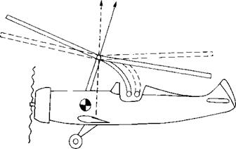
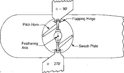
In the early Cierva autogiros, the rotor was simply a lifting device and roll and pitch control were obtained by ailerons on stub wings and by a conventional elevator, neither of which was very effective at low speed. Following his early successes, Cierva developed a means of obtaining direct control by tilting the rotor on a gimbal with respect to the shaft. With this scheme, pitch and roll control were generated by tilting the rotor thrust vector to give it a moment arm with respect to the center of gravity, as shown in Figure 3.26. This allowed Cierva to do away with the airplane control surfaces, but as autogiros became larger the control forces required to tilt the rotor became so high that flight was difficult. At this point, a means of rotor control called cyclic pitch was developed. In this system— which is almost universally used at present—the pilot cyclically changes the pitch of the blades about feathering bearings by tilting a mechanism known as a swash – plate. A schematic of this system is shown in Figure 3-27. It may be seen that if the swashplate is perpendicular to the rotor shaft, the blade angle is constant around the. azimuth, but that if the swashplate is tilted, the blade pitch will go through one complete feathering cycle each revolution. If the pilot pushes the stick forward, the swashplate is tilted forward. Since the pitch horn from the blade is attached to the swashplate 90° ahead, the blade has its pitch reduced when it is on the right side and has its pitch increased when it is on the left side. When the blade is over the nose or the tail, the forward tilt of the swashplate has no effect on the blade pitch.
Cyclic pitch can be used for two purposes: to trim the tip path plane with respect to the mast, and to produce control moments for maneuvering. In the first case, the pilot can mechanically change the angle of attack of the blades by the same amount as the flapping motion would have, thus eliminating the flapping. This can be used to eliminate all of the flapping or to leave just enough to balance pitching or rolling moments on the aircraft such as those due to an offset center of gravity.
|
T T
FIGURE 3.26 Pitch Control by Direct Rotor Tilt |
|
Thrust |
|
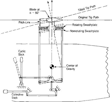
FIGURE 3.27 Schematic of Swashplate Control System |
In the second case, the pilot deliberately introduces an unbalanced lift distribution in order to make the rotor tilt for maneuvering. For example, if the helicopter is hovering and the pilot wishes to tilt the nose down, he pushes the stick forward, which tilts the swashplate down in front. The pitch of the blade at ф = 90° is decreased and that at ф = 270° is increased. The resultant imbalance accelerates the right-hand blade down and the left-hand blade up. The rotor flaps down over the nose and up over the tail, tilting the rotor thrust vector forward to produce a nose down pitching moment about the center of gravity, as shown in Figure 3.27. The procedure is similar if the pilot wishes to pitch nose up or to roll in either direction. Whether being used for trim or for control, the cyclic pitch is equivalent to flapping in that the changes in rotor conditions due to one degree of cyclic pitch are the same as those due to a one-degree change in flapping. Like the flapping, the blade pitch can be written’ in terms of a Fourier series:
0 = 0O + —- 0t — Ax cos у — Bx sin у К
where 0O is the average pitch at the center of rotation, 0t is linear twist, Ax is half the difference in pitch between the blade over the tail and the blade over the nose, taken as positive when the pitch at у = 180° is larger. Bx is half the difference in pitch between the advancing and retreating blades, taken as positive when the pitch on the retreating blade is gfeater than the pitch on the advancing blade. The coefficient, Ax, is called the lateral cyclic pitch because it is used by the pilot to produce rolling motion, and Bx is called longitudinal cyclic pitch because it is used to produce pitching motions. (This nomenclature is based on the results as the pilot sees them rather than on the geometry of the control system as seen by the designer.)
The use of cyclic pitch for trim makes it possible to eliminate the flapping hinges in the so-called rigid rotor designs. If a fully articulated rotor were trimmed with cyclic pitch so that the tip path plane was perpendicular to the rotor shaft, then it would be possible to freeze the flapping hinges with no change in the rotor condition, since there was no motion about the flapping hinges in the first place. Thus the flapping rotor with cyclic pitch could be converted into a rigid rotor with cyclic pitch. Similarly, if a rigid rotor were trimmed with cyclic pitch such that there were no cyclic flapping moments in the blade roots, then hinges could be introduced with no effect on the flight conditions. Thus the rigid rotor with cyclic pitch could be converted into an articulated rotor with cyclic pitch. From this, it may be seen that for the totor trimmed perpendicular to the mast, or nearly so, there is no essential difference between an articulated rotor and a rigid rotor. Where differences do exist will be discussed in Chapter 7.
Besides cyclic control, which the pilot obtains by tilting the swashplate with the cyclic stick held in his right hand, he has also the collective control that changes the pitch of all blades simultaneously by raising and lowering the entire swashplate. This is done with the collective stick, as shown in Figure 3.27.