Frequency response characteristics
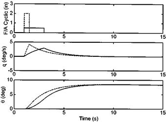
Before describing frequency domain testing methodology, it is necessary to discuss the conceptual background to the subject. When required to control a rotorcraft using single discrete inputs experienced pilots can compensate for attitude and rate delay by making a larger input initially (‘boosting’) and by ‘backing-off’ early or leading. The boost over-drives the aircraft response by generating a higher acceleration (although this will be limited by the control power available) and the lead allows the aircraft to settle at the desired attitude by removing the over-large input before its full effect can be realized, see Fig. 5.19. The dotted line shows the response of a typical helicopter to a large amplitude/short duration pulse and compares it to a more gentle input of lower magnitude but lower duration. Notice that in both cases the attitude change obtained is the same but the application of ‘lead’ has resulted in the target attitude being obtained some 5 seconds sooner. However when performing high-gain flying tasks, such as target-tracking, precision hovering or deck-landings the pilot will often
|
Fig. 5.19 Quickening the response by over-driving the control input. |
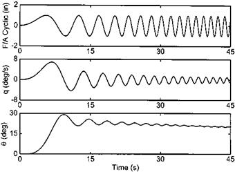
need to make continual small inputs to keep the aircraft on the desired flight path. In these situations, he may not be able to compensate adequately for excessive time delay since in trying to boost and lead he may find himself ‘out-of-phase’ with the aircraft. Consider the pitch response of a typical helicopter resulting from a constant amplitude frequency sweep, Fig. 5.20. After the initial gross attitude change (t > 10 s) note that as the input frequency is increased two effects are seen: the output (pitch rate or pitch attitude) changes in magnitude and it lags further behind the input. The qualities of gain and phase and their variation with input frequency are fundamental in shaping pilot opinion for high-gain handling tasks. Although presenting these trends in the
|
Fig. 5.20 Time history of a frequency response test. |
|
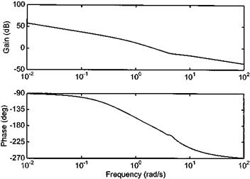
Fig. 5.21 Presenting frequency response data: Bode plot. |
form of time histories makes it easier to visualize them, this form of presentation is not conducive to detailed analysis or specification compliance testing.
Two methods of presenting frequency response information are commonly used: the Bode plot and the Nichols chart. These diagrams, originally developed for use in filter and other electronic component design, have found a place in handling qualities testing as the importance of frequency response characteristics has been realized. Nowadays they are not only convenient means of documenting these characteristics but are also used for detailing handling quality specifications [5.2 and 5.6]. The Bode plot consists of two charts with input frequency as the independent variable and either gain (ratio of output to input) or phase lag as the dependent variable, see Fig. 5.21. The Nichols chart presents both gain and phase information simultaneously, Fig. 5.22. Both formats result from a spectral analysis of time histories similar to those shown earlier.
It is important to consider what constitutes the most appropriate output for both spectral analysis and requirements specification. When the pilot moves the pitch/roll inceptor he will normally be targeting an attitude change and therefore the most obvious output for analysis would seem to be attitude. Indeed as shall be seen later attitude bandwidth is an important specification parameter. Experience has shown, however, that for good quality results it is necessary to use attitude rate in the spectral analysis process since there is usually a better spread of energy across the tested frequency range. After processing, it is a simple matter to reduce the gain by 20 dB/ decade and add the extra 90° phase lag associated with generating attitude from the integral of rate, see Fig. 5.23. This is usually a perfectly valid process provided the attitude excursions are not too large.


