Gas turbine engine and rotor characteristics
6.3.1.1 Rotor requirements
|
= * C I’5 s |
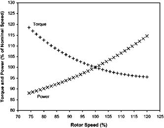
Sensibly constant RRPM is required both for mechanical reasons and for aerodynamic efficiency. If the RRPM is too high, Mach number problems are likely to be encountered on the advancing blade, whereas if the RRPM is too low, the stalled flow region on the retreating blade may become uncontrollable. If we restrict our consideration to the hover case then because we have removed the problems of asymmetry across the disk, the effect of variations in rotor speed on the power and torque required can be estimated quite easily using (see Figure 6.1):
|
Fig. 6.1 Rotor requirements. |
It can be seen from Fig. 6.1 that for a given thrust requirement a decrease in RRPM will have to be offset by an increase in the torque produced by the engine. Consequently matching the torque delivered by the powerplant to that required by the rotor will be simplified if the trend is similar. It should be noted that although a constant rotor speed is desirable, some variation in RRPM is likely particularly when the collective pitch lever is moved quickly. For optimum performance this transient should be as small as possible. However autorotative RRPM at minimum pitch should be as high as is possible to provide satisfactory engine-off landing characteristics.
6.3.1.2 Free turbine engine/rotor characteristics
The free turbine engine can be considered as two separate items: the gas generator and the power turbine. This is because in this type of engine the nozzle guide vanes at the front of the power turbine are always run in a choked condition (that is the flow Mach number equals unity at the throat of the nozzle guide vanes (NGVs)). Consequently the behaviour of the power turbine will not affect the performance of the gas generator. Thus the area of the choked NGVs will fix the position of the gas generator working line and the power turbine is supplied with a flow of high-energy gas that it can absorb at any combination of speed and torque. To understand how the overall engine characteristics are achieved it is necessary to consider the separate characteristics of the gas generator and of the power turbine.
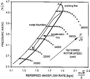
Figure 6.2 shows a typical compressor characteristic curve for a gas generator together with the operating or working line (which as has been seen above is positioned by the area of the power turbine’s NGVs). The stall margin is represented by the separation between the surge boundary and the working line. Points A and B indicate the areas where problems can be anticipated. Point A, the high NG/-J9 cross-over point, can usually by avoided by controlling maximum NG; but this point can give rise to problems under high altitude, low temperature conditions (low V9 values). On acceleration the stall margin at point B will be reduced as the acceleration line will
|
Fig. 6.2 Compressor characteristic. |
always be above the steady working line. A situation like that at B usually causes the difficulties associated with rapid engine acceleration requirements. Inlet guide vanes (IGVs) and/or bleed valves are used to increase the stall margin, but there are still likely to be limits set on the maximum rate of acceleration. Rapid increases in the combustion chamber pressure due to overfuelling must be controlled otherwise downstream choking may reduce the compressor air massflow rate and hence cause surge.
In some systems a compressor delivery pressure switch is incorporated that limits the fuel flow if the rate of increase of pressure is too high. The response rate of the gas generator is a most important factor when considering recovery from autorotation and although the gas generator of a free turbine engine is inferior in this respect to a fixed-shaft engine, modern gas generators fitted with anti-stall devices usually perform satisfactorily. Attempts to improve the power-to-weight ratio and the SFC will typically reduce the stall margin further, by moving the operating line closer to the surge line; acceleration thus becomes more critical. Any distortion of the compressor, casing or intake, caused either during manufacture or in flight (erosion or corrosion, FOD ingestion, ice build-up) will also narrow the stall margin.
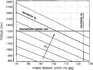
The torque versus speed (NF) curves for a typical power turbine are shown Fig. 6.3. The power turbine can operate anywhere in the area bounded by the maximum torque (a transmission limit), the maximum gas generator speed, and the maximum power turbine speed limits. The power produced at a given gas generator speed (NG) can be absorbed by the power turbine in any combination of torque and speed (NF) – hence the constant Ng lines are in fact lines of constant power. The pilot has two variables under his control: fuel flow via his throttle, which varies the gas generator speed (NG), and collective pitch that varies the torque demanded of the power turbine. Clearly if he has independent control of these two variables there is a distinct possibility that at some stage he will exceed the engine limits. For example, if he reduces throttle without
|
Fig. 6.3 Free power turbine characteristics. |
reducing the collective pitch the engine will surge, and it is imperative therefore that the two controls are interconnected so that this cannot happen. Two extremes are possible namely a constant speed power turbine/rotor schedule or a scheme that changes Nf so that at any gas generator speed the power turbine is operating at its most efficient. The acceleration obtained using the constant speeding schedule is usually better as power turbine and rotor inertia are not involved. However, the gas generator must still accelerate and as such is subject to the normal limitations of any jet engine. In early free turbine helicopters the rate at which one could apply collective pitch (effectively the aircraft manoeuvrability) was limited by the acceleration achievable by the gas generator. Modern engines are much improved in this respect.
The characteristics of the rotor and of the free turbine engine have now been considered separately. Combining the characteristics of the two systems for a given gas generator speed (NG) and a given flight condition gives us torque versus rotor RPM curves similar to those shown in Fig. 6.4. It can be seen from this figure that the free turbine characteristic matches the rotor requirement. If the RRPM falls then the free turbine will automatically compensate with an increase in torque for a given flight condition, such as the hover. The aircraft may well sink and therefore require a further power increase – this is not considered in the graph.


