Manoeuvre quickness
Before discussing how manoeuvre quickness is assessed it is perhaps worth reviewing the meaning of this relatively new handling quality parameter. Padfield reported [5.4] that efforts to resolve task portrait information with pilot commentary on handling
|
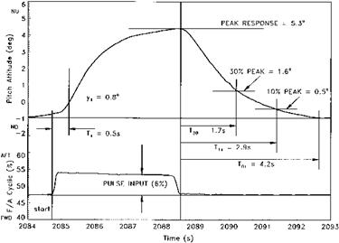
Fig. 5.13 Pulse response test data. |
qualities led to a realization that there was a range of control strategies for which neither bandwidth specifications (see the section on frequency analysis, Section 5.6) nor large amplitude specifications (see Section 5.5.4) were suitable. Either the input frequencies were too low or the task did not demand the use of the maximum angular rates available.
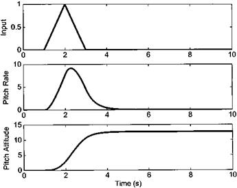
When developing the new parameter, that eventually became known as manoeuvre (or attitude) quickness, it was felt that it needed to correctly reflect the varying degrees of aggression with which the pilot could perform a specified flying task. During extensive trials, in both ground based and airborne simulators, it was noted that when pilots were asked to perform a manoeuvre requiring a discrete flight path or position change, such as a lateral side-step for example, each attitude change could be associated with a particular peak angular rate, see Fig. 5.14.
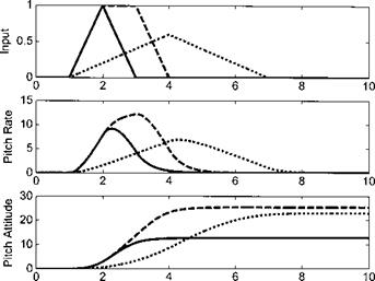
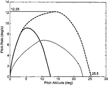
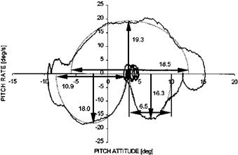
When pilots were asked to fly the manoeuvres more aggressively, or with more attack, it was found that the attitude changes were achieved with larger angular rates by the use of larger control inputs held for shorter periods of time. Referring to Fig. 5.15, note that two of the inputs portrayed result in broadly similar attitude changes: in both cases the helicopter attitude has been changed by approximately 25°. One trace shows the result of a 3-second pulse involving full control deflection whereas the other trace results from a 6-second pulse to 50% control travel. Clearly the first input is more aggressive than the second and this is characterized by a peak angular rate that is approximately twice as great. If a phase portrait is constructed for the manoeuvre, see Fig. 5.16, the difference in aggression is evidenced by the area under the curve (the greater the area, the higher the task aggression).
In developing manoeuvre quickness it was decided to use a parameter akin to frequency so that it would fit with the bandwidth criteria developed for control tasks requiring much smaller control inputs. In this way a more coherent scheme of handling qualities specification was achieved. The frequency parameter was obtained by dividing
|
Fig. 5.14 Trace of a discrete attitude change. |
|
Time (s) Fig. 5.15 Trace of attitudes changes with differing aggression. |
the magnitude of discrete attitude changes into the peak rate achieved during those changes.
In practice the assessment of the manoeuvre quickness characteristics of a helicopter is similar to pulse response testing although it is more common to analyze the effects of a series of control inputs rather than a single one. Typically the time history is obtained whilst executing a multi-axis task that requires the pilot to make inputs of
|
Fig. 5.16 Phase portraits of attitude changes. |
|
|
|
|
|
Fig. 5.17 Acceleration/deceleration test data. |
varying sizes at varying rates. Examples include flying a slalom course, executing an accel-decel (see Fig. 5.17) or NOE flight. Time histories of appropriate control, attitude and angular rate are then analyzed (as in Fig. 5.18). Discrete attitude changes and the peak rate generated during such changes can be identified and processed to produce
|
Fig. 5.18 Generating manoeuvre quickness data. |
values of manoeuvre or attitude quickness. Acquiring data suitable for specification compliance will involve incremental increases in the aggression with which the manoeuvres are flown. Typical aggression metrics are time taken to fly the course or maximum attitudes used during the manoeuvres. If the aircraft is capable of generating manoeuvre quickness in excess of that specified for a particular role or range of flight tasks it will be deemed to have Level 1 handling qualities.
5.5.4 Large amplitude manoeuvres
Large amplitude manoeuvre testing is required by ADS-33E [5.2] and involves exploring the maximum capabilities of the rotorcraft. In Table 5.2, example specification requirements are listed. It is evident that to generate the required angular rates or attitude changes large inputs will need to be made by the pilot. Full control deflections, more typical of fixed wing flying, may be required, therefore it is obvious that such testing will have to be approached incrementally using an appropriately instrumented airframe.


