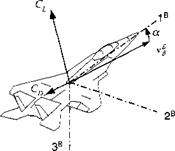
Planar aircraft
9.2.1.2 In five-DoF simulations an aircraft, executing bank – to-turn maneuvers, is assumed to do so at zero sideslip angle. The lift and drag
|
|
vectors lie in the load factor plane (see Fig. 9.5), and their aerodynamic tables are, therefore, only a function of the incidence angle a.
CL or Сц = f{M, a, power on/off}
A bank-to-tum autopilot provides this incidence angle a together with the bank angle фву – Because the symmetry plane coincides with the load factor plane, the transformation of the forces to body axes is like in Eq. (9.30) with the angle of attack a assuming the role of the total angle of attack a’
![]() Ca — —Ci sina + Co cosa Сц = Ci cos a + Co sin a
Ca — —Ci sina + Co cosa Сц = Ci cos a + Co sin a
When you read the newer literature,5 you will find the aerodynamic coefficient defined in the positive direction of the body axes, Cx and Cz■ They are in the opposite direction of Ca and Сц and are obtained from lift and drag coefficients by
![]() Cx = Ci sina — Co cos a
Cx = Ci sina — Co cos a
Cz = —Cl cosa — Co sina
In either case, the aerodynamic force vector for Newton’s equation is

![]() (9.35)
(9.35)
The trimmed aerodynamic tables of aircraft are usually built as functions of Mach and alpha. Several sets may be required for power on/off, or different configurations, like flaps in/out or gear in/out. Sometimes skin-friction corrections with altitude are also included.
The generic cruise missile simulation CADAC CRUISE5 can serve as an example. Its Cl and Cd tables are given as functions of Mach and angle of attack for three c. m. locations. With the turbojet engine providing continued thrust, we model only power-on drag. Let us now turn to the propulsive forces.


