Propulsion
Most of our needs for modeling thrust forces have already been covered in Sec. 8.2.4. The equations for rockets and combined-cycle airbreathing engines apply here as well. I will only expand on turbojet propulsion because it plays such an important role in cruise missiles and aircraft.
Review the section on turbojet propulsion in Chapter 8. The thrust formula
F = ma(Ve – V) (9.36)
(with V as the flight velocity, Ve the exhaust velocity, and ma the airflow rate) is commonly replaced by tables for thrust, fuel flow, and dynamic transients. We will work through an example that is used for cruise missiles and aircraft.
|
Cruise missiles have to maintain Mach number under maneuvers and environmental effects. Particularly challenging are the terrain-following and obstacle- avoidance flight patterns. We will model a Mach-number hold system suitable for cruise missiles and aircraft under such conditions.
The thrust required Fr to maintain a certain Mach number is equal to the drag force projected onto the centerline of the turbine. If the turbine axis is parallel to the body 1 axis, we require that
![]() qSCp cos a
qSCp cos a
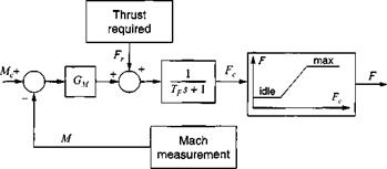
This value is used in the Mach hold control loop of Fig. 9.6. The commanded Mach number Mc is compared with the measured value M, and the difference is sent through a gain Gm that changes units to Newtons. The demanded thrust Fc is realized by the turbojet after spool-up or spool-down delays, characterized by the first-order lag time constant 7>. However, it may exceed the maximum possible thrust or drop below the idle thrust. Limiting tables restrict this excess demand. They are, in general, functions of Mach number and altitude. In simulations, the achieved thrust F is added to the right-hand side of Newton’s dynamic equations.
 |
The time constant 7> and the gain G ц are possibly a function of power setting. As an example, the spool-up time constant for the Falcon turbojet engine FI 00- PW-200 is between 7> = 0.2 —► 1.0 s. The gain can be calculated from a simple transfer function. We complete the control loop of Fig. 9.6 by the vehicle transfer functions, represented by the vehicle mass m B, an integrator, and the conversion to Mach number by the sonic speed Vs (see Fig. 9.7). The closed-loop transfer function is of second degree, characterized by the natural frequency oj„ and damping f. We
can eliminate con and solve for the gain
mB Vs
°M = 4W2
With Tf = 0.2 s given and f = 0.707 selected, the value for the Falcon is Gм =
3.4 x 10⁶.
Once the thrust F of the turbojet is given, we only have to determine the mass of the vehicle from the fuel consumed and the initial gross weight. The specific fuel consumption bf serves this purpose. It is usually given in tabular form as a function of Mach number and altitude. Multiplied by the thrust, it provides the fuel flow, which, integrated over time, supplies the expended fuel.
You can find the details of the implementation in the five-DoF cruise missile simulation CADAC CRUISE5 and the six-DoF simulation CADAC FALCON6. The engine decks are provided in English units, just to keep your unit conversion skills sharp.


