ROCKET3: Three-Stage Rocket Simulation
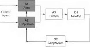
ROCKET3 is a derivative of GHAME3. Figure 8.18 shows the module structure. Only the shaded Modules A1 and A2 are different. I will be very brief in my description. After having thoroughly explored the GHAME3 model, you should have no problem deciphering the FORTRAN code of ROCKET3.
|
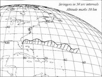
Fig. 8.16 GHAME3 hypersonic vehicle trajectory. |
The aerodynamics is modeled by simple polynomials in Mach number with linear dependency on angle of attack. The thrust for each stage is calculated from Eq. (8.24), then substituted into Eq. (8.25). Because we are dealing with liquid rockets, a throttle factor thr is inserted:
Ели = hvmgo thr + (psL – рмдК (8.32)
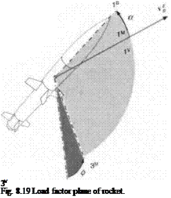
You may be puzzled by the fact that the A3 Module remains unchanged. For the earlier planar symmetry case, the airplane executes a perfect bank maneuver, maintaining its plane of symmetry in the load factor plane. Now look at Fig. 8.19. Conventional rockets and missiles, having tetragonal symmetry, do not bank to turn, but can generate a maneuver by pitch and lateral force. As a result, however, the load factor plane forms a roll angle wrt the vertical plane. This roll angle is
|
Fig. 8.17 GHAME3 trajectory parameters. |
 |
Fig. 8.18 ROCKET3 simulation modules.
the same as the bank angle of the aircraft. Therefore, ф serves as control input for both the aircraft and the missile, and we have no reason to change the A3 Module.
 |
You have become the master of simple point-mass, three-DoF simulations. I only carried through the Cartesian form of the equations of motion. It is left for you to implement the polar equations (see Problem 8.3). You should have an understanding of the standard atmosphere, gravitational attraction, and gravity acceleration. Simple drag polars model the aerodynamic forces, and the rate of change of linear momentum produces thrust. These elements of point-mass simulations are the basis for further development of more sophisticated five – and six-DoF models.
Problems
8.1 Three-stage rocket ascent to 300-km orbit. Task 1: Download the ROCKET3 simulation form the CADAC CD and run the test case INLAUNCH. ASC. Using CADAC-KPLOT, plot altitude, geographic and inertial speed, Mach number, dynamic pressure, heading, and flight-path angles vs time. Has the rocket reached orbital conditions?
Task 2: Now is your turn to lift the rocket to a 300-km near-circular orbit by scheduling angle of attack. Build the input file IN300.ASC. Can you achieve orbital conditions? Again plot altitude, geographic and inertial speed, Mach number, dynamic pressure, heading and flight-path angles, and angle of attack vs time.
Task 3: Summarize your findings in a brief ROCKET3 Trajectory Report. Include all plots and the input file IN300.ASC.
8.2 SSTO vehicle simulation. If you followed the CADAC Primer from the CADAC CD, you have already flown the GHAME3 simulation with the
INPUT. ASC file, but could not reach orbital conditions. With the rocket-propelled SSTO, launched from a Super Boeing 747, you can achieve a low-Earth orbit.
Task 1: Modify the A1 and A2 modules of the GHAME3 simulation, using the data SST03 from the CAD AC CD. The A1 and A2 modules are much simpler for the SSTO.
|
|
Task 2: Now, launch the SSTO from the Super B747 12 km above Cape Canaveral, Florida, horizontally in an easterly direction with |uf | = 253 m/s. Building the input file INCAPE. ASC with the following control commands for the ascent:
|
r, s |
a, deg |
thr |
|
<200 |
22.93 |
0.9 |
|
200-400 |
5.73 |
0.9 |
|
>400 |
5.73 |
0.5 |
At burn-out what are the values of |uf |, /, у, І, X, hi What is the inertial speed [u^]7, Kl? (Solution: t = 658 s, |uf| = 7442 m/s, / = 102°, у =6.4°, / = — 1.074 rad, A = 0.461 rad, and h = 106 km.)
Task 3: Next, repeat Task 2 for Vandenberg, California, but launch in a westerly direction. Build the input file INVAN. ASC and provide the same output.
Task 4: Repeat Tasks 2 and 3 for a nonrotating Earth.
Task 5: Write a summary report SST03 Ascent Trajectories. Provide all burnout conditions in one summary table. Include the input files. For Task 2 plot altitude, geographical and inertial speeds, flight-path angles, and fuel mass vs time.
8.3 SST03 simulation with polar equations of motion. In Sec. 8.1.2 I derived the equations of motion with the Earth as reference, while maintaining J2000 as the inertial frame. These equations should lead to the same results as the Cartesian formulation of Problem 8.2.
Task 1: Review Sec. 8.1.2 and code a new Module D1 with the polar equations of motion, Eqs. (8.11) and (8.12). Keep all other modules of the SST03 unchanged. Verify that all changes are made correctly by using MKHEAD3.EXE.
Task 2: Use the input file INCAP. ASC from Problem 8.2 and run your polar SSTO3 simulations. The endpoint parameters should agree with less than 1 % error. Plot the Coriolis and centrifugal accelerations and compare them to the gravitational term. Plot these three variables vs time. What conclusions do you draw?
Task 3: Summarize your work in the SSTO Polar Simulation Report. Document your D1 Module, show your plots, and discuss your findings.


