Skid-to-tum incidence angles and rates. I
n the skid-to-turn case the angle of attack and sideslip angles determine the deviation of the velocity vector from the centerline of the vehicle. However, we must use the velocity vector of the vehicle relative to the air mass instead of the inertial frame because incidence angles are used in conjunction with the aerodynamics of the vehicle. We name
|
|
|

this velocity frame V and the associated geographic velocity vector v§, i. e„ the velocity of the c. m. of the vehicle В wrt the Earth E.
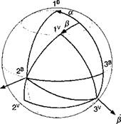
The body axes ]® are associated with the body frame B, and their positive direction is defined as follows: 1® is the body centerline, 2® the right wing, and 3® points down.
The geographic velocity axes ]v are associated with the geographic velocity frame V and given by 1v as the velocity vector, 2V in 1G, 2° horizontal plane.
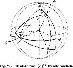
The incidence angles are a as the angle of attack and /3 as the sideslip angle. Refer to Fig. 9.2 and compare it to Fig. 3.17 in Chapter 3 to confirm that the incidence angles are the same. The sequence of transformation is ]®<—]•<— ]v. Notice the negative sense of the transformation of the sideslip angle. The transformation matrix between the body and geographic velocity coordinates is
cos a cos P —cos a sin —sin a
![]() [T]BV = sin/1 cos /3 0
[T]BV = sin/1 cos /3 0
sin a cos /3 — sin a sin /3 cos a
It is the same for our pseudo-five-DoF treatment as for the full-up six-DoF simulations (see Chapter 10).
The angular velocity of the body frame wrt the geographic velocity frame is derived from Fig. 9.2. Combining the incidence rates with their respective unit vectors and adding them vectorially yields
Expressed in body coordinates
[0)®T =$[T]BV[U3]V +a[b2]B
and evaluated with the help of Eq. (9.8)

The angular velocity of the body frame wrt the geographic velocity frame is a function of the incidence angular rates and the angle of attack, but not of the sideslip angle. Both the angular rates and the angle of attack are given by the transfer functions of the autopilot.


