Test methodology
An ideal frequency sweep comprises a continuous, constant-amplitude sinusoidal control input at progressively increasing frequency. The characteristics of a good
|
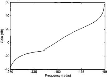
Fig. 5.22 Presenting frequency response data: Nichols chart. |
|
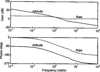
Fig. 5.23 Frequency response of attitude from angular rate test data. |
frequency sweep, and the techniques that should be employed to achieve them, are detailed below.
5.6.2.1 Amplitude
Ideally the frequency sweep should be made using a constant amplitude control movement. It is very easy for the pilot to inadvertently increase input amplitude as frequency increases. This is often due to the greater forces that are required to overcome viscous damping effects in the control linkage. Increased amplitude at high frequency should be avoided as it may cause structural damage to the airframe. The use of two hands on the cyclic helps as do high bandwidth, fast-acting control position indicators. A mechanical device similar to a ‘two-way control fixture’ may also be used but there is a risk of squaring off the input peaks (with consequent corruption of the frequency spectrum) if the control is allowed to actually touch the fixture.


