Tetragonal missiles
A tetragonal missile’s aerodynamics is only weakly dependent on the roll orientation of the body. For simple pseudo-five-DoF simulations, we neglected that effect altogether and are left only with the total incidence angle a’:
CL or Сд = f{M, a!, power on/off}
If the missile executes skid-to-tum maneuvers, the autopilot provides a and f information, which is converted to aeroballistic incidence angles by Eq. (3.24):
The lift vector is normal to the velocity vector in the load factor plane and is a function of a’. Many missile simulations require the forces to be expressed in body coordinates. We make the conversion in two steps. First, we transform lift and drag to normal force and axial force coefficients in aeroballistic wind coordinates through the angle a’
CA> = —Ci sin a’ + CD cos a’
![]() CN> = Ci cos a’ + Сд sin a’
CN> = Ci cos a’ + Сд sin a’
followed by the rotation through the angle ф’ to body fixed axes
CA = Ca’
Cy = — Cn> sin ф’ (9.31)
CN — CN> cos ф’
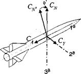
Let us pause and point out the difference between the aeroballistic ф’ of Fig. 9.4 and the bank angle фву of Fig. 9.3. Both are transformation angles about a 1 axis, but in the case of ф’ it is the body axis and for фву it is the velocity vector.
The aerodynamic force vector for Newton’s equations is now in body axes
|
Fig. 9.4 Transformation of aeroballistic wrt body axes. |
Notice the negative directions of Ca and C v relative to the positive directions of the body axes. This convention is universally used for missiles and has its origin in the definition of positive lift and drag.
The aerodynamic tables of a typical air-to-air missile are a function of Mach, total angle of attack a’, and power on/off. For the sample simulation CAD AC SRAAM5, I also included skin-friction drag corrections caused by altitude changes. To improve the realism even more and recognizing the large change in mass properties during fly-out, I included the tables for three c. m. positions: fore, middle, and aft. They represent the changing trim drag caused by control deflections and are interpolated during thrusting.
In some applications you may be given the aerodynamic tables directly in normal and axial force coefficients. If that is the case, you just bypass Eq. (9.30) and continue by converting the coefficients to body axes with the transformation Eq. (9.31).
We have defined the load factor plane as the plane containing the lift vector of a tetragonal skid-to-turn missile. Turning to planar aircraft, including cruise missiles, this arrangement is particularly advantageous.


