Trimmed flight control positions tests
Determining the theoretical variation of longitudinal cyclic pitch, and pitch attitude, with trimmed airspeed is more difficult. The control deflection required and the aircraft attitude is dictated by the requirement to achieve equilibrium of both forces and moments whilst maintaining level flight. Basically equations arising from considering equilibrium of X-force, Z-force and M-moment are obtained. At each trim condition these equations are solved simultaneously to give values for longitudinal flapping, relative to the shaft (als), pitch attitude (0) and thrust. These are then used to determine the longitudinal cyclic pitch (Bl) and cyclic stick position required. On a conventional helicopter the M0c effect on cyclic position will be the same as those seen during steady climbs and descents at the same collective pitch and off-trim airspeed. A forward longitudinal control displacement or force should be required in order to initiate and maintain an increased forward airspeed [5.1]. Pitch attitude variation with airspeed will typically be a compromise between maintaining a near level attitude for crew comfort and profile drag considerations, whilst achieving pitch attitudes relatable to airspeeds for instrument flight.
5.2.1.2 Practical considerations
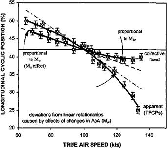
Provided only small speed changes are made during collective fixed static stability (CFSS) testing, and the same range of airspeeds are evaluated during a TFCP test, the effect of changes in collective pitch or power (M0 ) can be evaluated by direct comparison. Consider Fig. 5.4 which shows the typical case of a helicopter with a nose-up trim change with increased power (collective). Above minimum power speed the pilot must increase collective pitch to generate sufficient thrust to maintain level flight at higher speeds. He must now apply extra forward cyclic, to counter the nose-up cross-coupling effect over and above that required to overcome the basic pitch-up tendency with increased speed (flap-back effect). Static stability test results would, therefore, show ‘increased stability’ when TFCP results were compared with data obtained from a collective fixed test. Note that the speed stability, or Mu effect, can also be clearly seen by comparing the collective fixed test data with a horizontal line from the trim point (Mu = 0). The non-linear nature of the M0c effect can be explained with reference to a typical power curve where the power decrement required to maintain a lower speed in level flight reduces as the minimum power speed is approached.
CFSS tests are normally accomplished by establishing a trim condition (airspeed/
|
Fig. 5.4 Longitudinal static stability test data. |
power combination) with zero control forces. Then without changing the collective position, trim setting or rotor speed, the helicopter is stabilized at incremental airspeeds both faster and slower than the trim airspeed using cyclic only. Directional control inputs are made to maintain ball centred or zero sideslip flight. An airspeed range either side of trim is assessed using 2 knot then 5 knot increments. Ideally the helicopter is kept within 1000 feet of the specified test altitude. Airspeeds faster or slower than trim are flown alternately to achieve this. Excursions from the test altitude band can be corrected using the collective control. To achieve this the collective trim position or power/torque for level flight at the datum speed is noted. Collective pitch is then used as required to regain the desired altitude and, without re-trimming the cyclic, is adjusted back to its initial position before the test is continued.
Although, as discussed, the collective to pitch coupling can be discerned by comparison between TFCP testing in level flight and collective fixed data, the coupling can also be evaluated by performing trimmed climbs and descents at constant airspeed. As well as highlighting any problems with excessive collective-to-pitch cross-coupling these tests will identify the possibility of an encroachment of control margins. Discontinuities in the collective position versus longitudinal control position data may suggest handling problems caused by, for example, the stalling of a down-loaded tailplane at high negative angles of attack which may occur at high ROC and low IAS. TFCPs are normally evaluated at a number of key role-relatable airspeeds such as climbing/endurance/autorotation speed, cruise speed and maximum level flight speed. Since M0c increases with airspeed it is normal to evaluate the lower speeds first.
In summary, during static (speed) stability tests the aim is to identify the Mu effect (collective fixed) and the M0c effect (TFCPs in climbs/descents and collective fixed versus TFCPs in level flight). If, however, during these tests the angle of attack changes markedly from its value at the trim point (level flight at the trim speed) it is possible that Mw effects will corrupt the results. Typical advice is therefore to only test modest deviations from trim ( + 15 kts for collective fixed static stability tests and +1000 fpm for TFCPs in climbs/descents).


