Proportional navigation
. Proportional navigation (PN) is as old as the seafaring mariners who knew that a collision will occur if another vessel maintained its beam position. Pirates used that principle to intercept their bounty. Today’s missiles use PN to intercept targets.
|
Intercept
Fig. 9.21 Engagement triangle. |
The earliest applications go back to the end of World War II and were reported by the Naval Research Lab17 and later extended by the Massachusetts Institute of Technology in a formerly classified report.18 Ever since, PN has been the premier guidance law, particularly for air-to-air missiles. I do not know of any interceptor that does not employ some form of this guidance scheme.
The displacement vector of the target c. m. T wrtthe missile c. m. B, sTB, is called the line-of-sight (LOS) vector. Its orientation will remain fixed in inertial space if the missile is on a collision course. The other important vector is the differential velocity VgT of the missile c. m. В wrt the target frame T, which is obtained from the inertial velocities of the missile and the target
vfr = vf-v£ (9.51)
(For a discussion of differential and relative velocities, refer back to Example 4.17). The Earth serves here as an inertial frame. As long as the relative velocity vector is pointing at the target, i. e., parallel to the LOS, an intercept will occur (assuming constant velocities). This engagement triangle is shown in Fig. 9.21. Although it is valid in three dimensions, let us consider it from a two-dimensional standpoint. The flight-path angle у and the LOS angle к are defined wrt an inertial datum. These angles must remain constant for the intercept. If the target maneuvers evasively, the missile velocity vector must be adjusted according to the change in LOS angle. For instance, if the target speeds up, к increases, and, therefore, у must be increased in order to maintain the engagement triangle. In other words, the time rate of change of у must be made proportional to the time rate of change of k, i. e.,
у = Nk (9.52)
with the navigation ratio N as the proportionality constant. Equation (9.52) is the famous PN relationship. The navigation ratio determines the lead of the missile velocity vector wrt the target. For most missiles it is given the value between two and four. Modern optimal control assigns it the value three.16
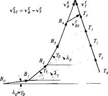
Let us look at Fig. 9.22 and follow an engagement that starts outside the engagement triangle. Assume that missile and target velocities are constant. Initially, the missile Bq flies directly toward the target To, and the glide-path angle yo equals the LOS angle ко – The advancing target turns the LOS and generates a k, which, magnified by N, turns the missile by у. Now, y > k, and the missile’s flight-path
|
Intercept
Fig. 9.22 Engagement starting from arbitrary initial conditions. |
angle starts to lead the LOS angle. Eventually, the engagement triangle does not change shape and A = 0, у = 0 until intercept.
In applications the LOS rate A is measured by the missile seeker and converted through the PN law into the acceleration command for the autopilot. The missing link is the relationship between у and acceleration a. We derive it from the fact that the acceleration normal to the missile velocity vector vf is (with V = |i>f |)
a = Vy (9.53)
and we obtain with Eq. (9.52) the steering command for the autopilot
a = NVA (9.54)
This relationship applies only to planar engagements. The extension to the three – dimensional case follows by similitude. The angular velocity vector of the LOS frame О wrt the inertial Earth frame E is ш0Е, and the angular velocity vector of the velocity vector vf wrt Earth is u>VE. Following Eq. (9.52), we formulate in three dimensions
uVE = Nujoe (9.55)
Furthermore, taking our cue from Eq. (9.53), the acceleration a normal to the missile velocity is proportional to the cross product of uiVE and the unit vector u, ofvf:
a = VflVEuv (9.56)
Substituting Eq. (9.55) into the last relationship yields the acceleration command
a = NVCl0Euv — g (9.57)
with the added gravity bias term g. Without this term and no signal from the seeker, zero acceleration would be commanded, resulting in a ballistic trajectory.
The g-bias term counteracts the sagging tendency of the trajectory under seeker control.
This form of PN has been given the special designation pure PN19 and is characterized by the fact that the acceleration command is normal to the inertial missile velocity vector vf. Another form, the so-called true PN,19 generates its acceleration command normal to the relative velocity vector vfr. It has the same form as pure PN, portrayed in Eq. (9.57), except that uv is taken as the unit vector of vfr and V = |ufr|.
Let us pause, sit back, and look at the effect that a rotating round Earth can have on the PN implementation. Certainly, the angular velocity of the Earth is negligible wrt the rapidly changing LOS rate of a missile engagement. Therefore, the preceding equations are equally valid for the rotating Earth case.
For practical applications the inertial LOS rates ш0Е and the unit velocity vector are given in body axes, whereas the gravity bias is expressed in local-level axes (or geographic axes for round-rotating Earth). The acceleration command to the autopilot must be delivered in body axes:
[a]B = NV[n0E]B[uv}B – [T]BL[g]L (9.58)
Full information awareness is assumed. The INS provides [T]BL. The seeker delivers [w0E]B and, in addition, [uv]B fortrue PN. Some simplifications are possible. If the acceleration levels of the engagements are high, like in close-in combat, gravity can be neglected, and therefore [T]BL is not needed. Infrared imaging seekers do not deliver full target-missile kinematics as radio frequency seekers do. Therefore, if the relative LOS vector cannot be constructed, pure PN is implemented and [uv]B calculated from INS data.


