Rate command or attitude command and attitude hold
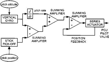
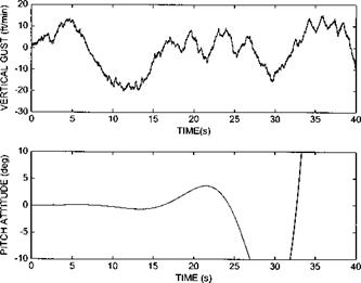
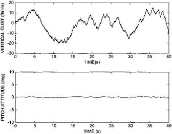
Complete elimination of all long-term ‘nuisance’ modes requires accurate attitude information and so a device sensitive to aircraft attitude, a vertical gyro for example, is used to feed the series actuator (see Fig. 6.23). The power of accurate attitude feedback can be demonstrated by reference to the longitudinal dynamics of the example helicopter when excited by gusts in the form of vertical turbulence. Without attitude stabilization the unstable long-term mode is revealed (see Fig. 6.24). If unity attitude feedback is used this mode is easily stabilized (Fig. 6.25).
As suggested earlier the challenge for the AFCS designer is in obtaining the right
|
Fig. 6.23 Block diagram of a typical attitude-based stability augmentation system. |
|
Fig. 6.24 Unaugmented gust response of example helicopter (note the у-axis scaling set for comparative purposes). |
|
Fig. 6.25 Gust response of AFCS with unity attitude feedback. |
compromise between gust rejection and control response. In its current form the modelled AFCS would completely oppose the pilot since it would treat any pilot induced attitude change as an unwanted deviation from datum. Indeed if the series actuator has sufficient authority it will return the cyclic pitch at the rotor head to the value extant before the pilot made the input. It has already been noted that angular rate feedback can improve the control response by reducing the time constant and enhance gust rejection by generating an error signal before the aircraft attitude has deviated significantly from the datum. Thus a satisfactory situation usually results if pitch or roll attitude is differentiated, or the angular rate is measured directly, and used as an additional error signal provided the attitude feedback signal is inoperative during pilot inputs. The manner in which the attitude signal is disabled will dictate whether the AFCS provides rate command or attitude command.
Two basic methods exist: one uses a signal from the stick to switch out the attitude feedback loop whilst the other uses the signal to update the attitude datum. A microswitch placed in the spring-feel unit that only allows attitude feedback when the aircraft is trimmed is an example of the former whereas a device that generates a signal in opposition to the attitude error coming from the gyro (a stick-canceller) is an example of the latter. The microswitch approach would provide the pilot with RCAH provided he is happy to manoeuvre the aircraft without re-trimming and then use a trim-release switch to rapidly re-centre the spring-feel unit. Such a mechanization would also require storage of the datum attitude in some form of memory with the stored value being updated as the cyclic stick is moved against the trim springs.
The stick-canceller approach operates by converting stick position into an attitude command that is used to oppose, or cancel, the signal from the attitude sensor. With this type of AFCS, therefore, a step input results in the aircraft capturing a new attitude and thus provides the pilot with the ACAH response type. Another consequence of using a signal from the stick to oppose a steady error signal from the vertical gyro manifests itself during the initial phase on a control input as ‘control quickening’. In
|
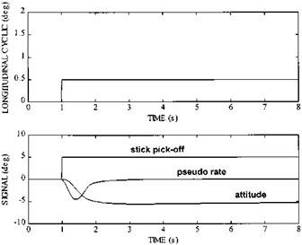
Fig. 6.26 Effect of rate feedback and stick cancellation on actuator drive signals. |
order to function correctly the position signal from the pick-off must oppose that coming from the gyro and the series actuator must oppose any angular disturbances sensed by the gyro. The net effect of subtracting the stick signal from the gyro and feeding the result to the series actuator is that the contribution from the stick pick-off becomes additive whereas that from the gyro remains subtractive. Therefore, if the pilot moves the stick rapidly from trim the series actuator will move initially in the same direction. It will only begin to oppose the input when sufficient angular rate and attitude changes have developed (see Fig. 6.26). Note that the series actuator drive signal will be the sum of the three signals presented.


