Static droop and governor gain
As mentioned earlier the use of a simple hydro-mechanical proportional governor to control rotor speed leads to reductions in RRPM as the fuel flow increases and vice- versa. This trend manifests itself as static droop, that is as the torque is increased from one equilibrium point to another the rotor will stabilize at lower and lower speeds. The amount of static droop can be expressed as:
![]() RRPM at minimum power — RRPM at maximum power _ 1 n(W
RRPM at minimum power — RRPM at maximum power _ 1 n(W
тТ"гТт^тГТ • • X 100%
RRPM at minimum power
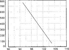
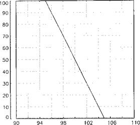
The change in fuel flow rate with RRPM (the static droop law) can be portrayed in a variety of ways and two typical plots are shown in Fig. 6.6. Although static droops as high as 10% have been used it should be remembered that for optimum rotor performance no change in RRPM, or isochronous governing, is desired. The problems associated with trying to achieve such governing by reducing the static droop are discussed below.
Governor gain is related directly to the amount of static droop. The gain is the change in fuel flow rate per unit change in RRPM. Thus a system with low governor gain will generate a high static droop and vice-versa. Consider now the effect of high governor gain, which is analogous to fitting a weak spring in a proportional governor. Although under static conditions the difference in RRPM between low and high torque settings will be low, the large changes in FFR that occur for small changes in RRPM can lead to an oscillatory and possibly unstable response. Figure 6.7 shows departures from the static droop law. Note that the oscillatory behaviour commonly associated with high gain is quite evident. (Lower chart in Figure 6.7.)
Selecting the best value for governor gain is a compromise between desired levels of stability and the need to remain within rotor limits during rapid power changes. However, the expected maximum rate of application of collective and available engine response must also be considered. Suppose the pilot moves the collective at a moderate
|
ROTOR SPEED (%) |
|
POWER TURBINE SPEED (%) |
Fig. 6.6 Static droop.
rate and the engine is capable of rapid acceleration then it is possible for the control system to produce a response with no transient. If on the other hand the pilot makes a very rapid demand a transient will result if the demand exceeds the acceleration capabilities of the fuel control system.


