The control axis
There exists a third axis, not parallel to the disc axis in translational flight, about which no blade feathering takes place. This is called the control axis, and it is the hardest one to visualize. An observer turning with the control axis in forward flight would note that the pitch of the blades was constant, but that the blades flapped up at the advancing side of the nose of the machine and down at the retreating side of the tail. A given blade would appear to drag back when advancing, and then forward when retreating. The dragging would appear much greater than in the case of the observer on the disc axis.
As Figure 4.3(b) shows, in the special case of a two-bladed rotor, if the pitch control rods stay parallel to the mast and are at 90° to the blades, the swashplate also rotates on the control axis. The blade stays parallel to the swashplate and so cannot feather with respect to it. In the general case the control axis and the swashplate axes are not the same as will be seen in section 4.13.
There is an exact equivalence between the degree of flapping seen by an observer on the control axis and the degree of feathering seen by an observer on the tip path axis. Figure 4.3(c) shows that when the control and tip path axes differ by в°, if the blades reach a peak feathering angle of в ° with respect to the tip path axis, they will flap to a peak deflection of в° with respect to the control axis.
The reason for the difference between the tip path axis and the control axis should now be clear. In the hover, there would be no permanent difference as the blades follow the cyclic stick. However, in translational flight, the blades encounter highly asymmetrical conditions that pull the tip path axis away from the control axis. In order to fly straight and level, the pilot has to find a position for the cyclic stick in which the asymmetrical conditions on the blades are precisely opposed by cyclic input so that the rotor disc attitude is no longer affected by the asymmetry. For example, if at a certain airspeed the advancing/retreating effect would result in three degrees of flapback, the application of three degrees of forward cyclic will put the rotor disc back in the attitude it would have had in the absence of flapback.
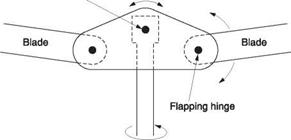
As the shaft axis and the tip path axes can be non-parallel, clearly some joints or bearings are necessary or something must be designed to flex. The flapping and lagging bearings in an articulated head approximate to a constant velocity joint between the shaft axis and the tip path axis. The spherical bearing in the centre of the swashplate and the feathering bearings in the rotor head allow the control axis to be different from the shaft axis.
The motion of the blades can be studied with respect to any one of the above axes. Each has its own merits. The use of the control axis is instructive when studying the
helicopter in detail. For hingeless rotors use of the shaft axis has some advantages but the tip path axis excels when discussing articulated and teetering heads because it is easier to visualize what is taking place and the direction of the resultant rotor thrust is clear. It is best used for flying training because it is most tangible to pilots. In practice it is useful to be able to switch conceptually from one axis to another to obtain a proper understanding.
The control axis was naturally used in the study of the autogyro and as the theory of the helicopter was in many ways derived from work done on the autogyro much early helicopter analysis also uses the control axis, including the classic work by Gessow and Myers.1 Although the authors make it perfectly clear that the control axis is being used as a reference, not every reader understands what that means and there is scope for misunderstanding if the axes become confused. One example is the occurrence of numerous explanations that are seen claiming that flapping hinges prevent asymmetry of lift in translational flight in gyroplanes and helicopters. This is complete nonsense and comes about because the tip path and control axes have been confused. The blades can flap with respect to the control axis without any flapping hinges or flexibility at all simply because the control axis is not parallel to the tip path axis.
It is important to appreciate that all of these axes are hypothetical and the rotor doesn’t care how we choose to observe it. Thus whatever axis is used for analysis the result must always be consistent with the result of an analysis on another axis. To give an example, as the blade pitch appears constant to an observer on the control axis, no force is necessary to make the blades perform cyclic pitch changes other than to overcome friction in the feathering bearings. If the same analysis is carried out on the tip path axis, the blades appear to be oscillating along the feathering axis. The effect shown in Figure 3.8 produces a restoring action tending to return the blades to flat pitch. This causes the blades to have a torsional resonant frequency. It can be shown that this is the same as the rotational frequency of the rotor. As a result the feathering blades are in torsional resonance and so no force is required to operate them other than to overcome friction. This is consistent with the analysis on the control axis.
If harmonic pitch control is used, then strictly there is no axis about which the blades do not feather. However, the control axis could be redefined as the axis about which there is no first harmonic feathering. In other words only the higher harmonics of feathering would be seen with respect to the control axis. This is a reasonable approach because the tip path plane is not really a plane чbecause of flapping harmonics and yet the concept is still useful. Interestingly with the correcчt application of harmonic pitch control the feathering will see more harmonics so that the tip path may see fewer.
Flapping is the movement of the blade CM along the shaft axis. It was shown in section 2.14 that the fundamental resonant frequency of the flapping blade is almost the same as the rotational frequency. With a zero-offset rotor the frequencies are identical and this results in a 90° phase lag in the rotor. When flapping hinge offset is used, the resonant flapping frequency rises slightly because the blades become a little shorter without the diameter changing and the result is that the phase lag of the rotor becomes a little less than 90°. This is compensated for in the design of the controls.
Flapping is self-damping because of the effect it has on relative airflow. When a blade flaps down, its vertical velocity adds vectorially to the airflow to increase the angle of attack, providing more lift to oppose the flapping. When a blade flaps up, the
opposite occurs. As a result no additional damping is required about the flapping axis, aerodynamic damping being perfectly adequate.
When a rotor is turning at flight RPM, centrifugal stiffening tends to hold the blades straight and they will cone to whatever angle is necessary for a force balance in the rotor head. With flapping hinge offset, if the tip path plane tilts, a couple will be created which tilts the hull to follow. As a result the freely flapping blades will not strike the tail boom. There have been some spectacular incidents in wind tunnels where the hull of the helicopter was fixed and this mechanism could not operate.
As a rotor slows down, the blades will droop and stops are needed to restrict the travel. These can be fixed if a tall mast is used. However, Figure 4.4 shows that at flight RPM the blades are nearly straight whereas at rest they droop. Thus the actual angular motion allowable at the head is greater when the blades are turning. This requirement can be met by using moving droop stops which are thrown out of engagement as the rotor speeds up, and which return under the influence of springs as it slows down. Stops are also required to restrict the upward motion of the blade if it ‘sails’ whilst starting up in a wind.
In the absence of coning, the flapping hinges would be sufficient for the shaft axis to tilt with respect to the tip path axis, but greater freedom is needed in the presence of coning. Figure 4.5 shows an example of a machine hovering with the CM not directly below the rotor head so that the mast is not vertical. When viewed along the tip path axis at (a), the blades are evenly spaced, but when viewed along the shaft axis (b), the blades are not evenly spaced, and dragging hinges are necessary to allow this angular change with respect to the rotor head so that the blades can travel at constant velocity to conserve momentum. If the blades were not allowed to drag, they would experience alternating bending moments due to the geometrical conflict.
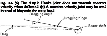
The dragging motion in the hover is due to the rotor head turning on the shaft axis whilst the blades turn on the tip path axis. If a flexible joint were installed in the rotor shaft, the rotor head could turn on the same axis as the blades and then there would be no dragging movement due to coning and no need for dragging hinges. A simple flexible joint such as the Hooke or universal joint used in automotive propeller shafts
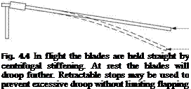 Turning blade will be straight
Parked blade will droop
|
Fig. 4.5 When viewed along the tip path axis, the blades are 90° apart in the hover, but if the CM is offset, the shaft axis and the tip path axis are not aligned. With respect to the shaft axis the blades are not evenly spaced. Dragging hinges allow this geometric conflict to be resolved. |
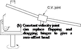
is shown in Figure 4.6(a). This, however, does not give constant angular velocity when it is deflected and this would cause torsional stress in the transmission. What is needed is a true constant velocity joint of the type used in front-wheel-drive cars. In the LZ-5 helicopter designed by Glidden Doman a true constant velocity joint was used (b).
A rotor head having only a constant velocity joint would not be able to transmit any moments to the mast and so would be classified as a zero-offset head. Such heads are only suitable for lightweight machines. However, it would be possible to fit springs to the head to give it some ability to transmit moments.
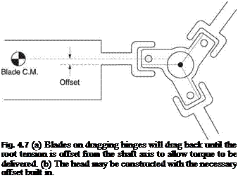
Clearly the blades are being driven through the air by torque supplied to the rotor head. In an articulated head the dragging bearings prevent torque being transmitted to the blades. The blades actually drag back until the blade tension applied to the rotor head is no longer truly radial but is displaced with respect to the mast axis. Figure 4.7(a) shows that this results in the torque from the transmission being balanced in the rotor head. The rotor head will often be constructed with a typical offset built in as shown in (b).
Note that the blade grip attaches to the blade on the axis of the mass centroid of the blade so that no bending stress is caused at the mounting. As the mass centroid is
 |
(a)
(b)
set forward to about 25% of the chord for stability, the attachment point will also be forward of the mid-chord point.
When a blade flaps up, perhaps in response to a cyclic input, the centre of mass of the blade moves towards the shaft and conservation of momentum causes the blade to accelerate in the disc plane. This explanation is for a stationary frame of reference. However, in a rotating frame of reference, the blade appears to be stationary and has no momentum. In order to explain how it appears to move forward a virtual force,
called a Coriolis force, has to be imagined to act. If the head itself is completely rigid, the in-plane blade movement due to conservation of momentum results in bending in the blade. The resultant forces are often called Coriolis forces. In fact the forces arise because the rigid head tends to prevent the blade conserving its momentum whereas drag hinges allow momentum to be conserved.
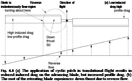
In translational flight there is considerable asymmetry in the conditions experienced by the advancing and retreating blades. The most obvious consequence of this asymmetry is the application of cyclic pitch in order to produce equal lift moments on each side of the rotor. This will result in the induced drag and the profile drag being functions of blade phase angle and radius. Note that these two functions are quite different. Figure 4.8 shows that the induced drag falls on the advancing blade because the angle of attack is reduced, whereas the profile drag increases because the velocity of the RAF is higher. Figure 4.8 shows that, at an inboard radius, reverse flow causes the root end of the blade to develop an undesirable down force.
The result of these induced and profile drag variations will be in-plane bending moments within the blade as well as overall in-plane moments at the blade root. Dragging hinges are intended to relieve in-plane root moments. However, the presence of dragging hinges allows in-plane blade motion and it is important that this motion is stable. Unlike flapping, the restoring force when the blade drags away from its neutral position is quite small and so the resonant frequency is much lower than the rotational frequency. For in-plane motion, the degree of aerodynamic damping is also very small. It was seen in Chapter 1 that additional damping is often necessary on the dragging axis to prevent ground resonance. This phenomenon will be discussed in sections 4.16 and 4.17.
The order in which the flapping, dragging and feathering hinges are disposed is subject to a certain amount of variation from one design authority to the next. The use of coincident flapping and dragging axes is common because it allows a compact bearing
assembly that is particularly important on multi-blade heads, where the head can become a serious source of drag if it is larger than necessary. Figure 4.2 showed an example of a head in which the flapping and dragging hinges are combined in a single Hooke joint having a cruciform central member. The logical place for the feathering bearing is outboard.
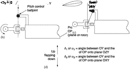 |
Figure 4.9(a) shows that the three hinge axes are not necessarily orthogonal. This results in coupling between the axes, sometimes deliberate, sometimes an unavoidable geometric compromise. A hinge has an axis and this can only uniquely be defined in three dimensions. In Figure 4.9(a) O is the rotor head, OZ is the rotor shaft axis and OX is the blade span axis. OXY is the plane of the rotor. In an orthogonal head, OY would be the flapping axis, OZ would be the dragging axis and OX the feathering axis.
Fig. 4.9 (a) The axes of hinges in the head are not always orthogonal. Two of the axes may be turned as shown by amounts delta-1 and delta-3. (b) To avoid coupling between flapping and feathering, the pitch change rod must terminate on the flapping hinge axis. (c) The pitch change rod may terminate outboard of the flapping axis. This results in a delta-3 effect (d).
OP is an arbitrary hinge axis and could be a flapping or a lagging hinge. In the literature, the flapping hinge is called the 8 hinge and the dragging hinge is called the a hinge. These hinges can be turned away from the mutually orthogonal in three axes, 1, 2 and 3. Only two of these axes are shown in Figure 4.9(a); axis 2 is redundant. If OP is a flapping hinge and is projected into the plane of the rotor, OXY, the angle between the projection and OY is called 83 (delta-three). If OP is projected onto the plane OZY, the angle between the projection and OY is 81 (delta-one). In an orthogonal head these angles are both zero.
Figure 4.9(b) shows that to avoid coupling between flapping and feathering, the spherical bearing between the pitch control rod and the pitch control arm must be on the axis of the flapping hinge which must also be at 90° to the feathering axis.
The pitch control arm is generally on the leading edge of the blade. If the pitch control arm is made slightly shorter as in Figure 4.9(c), there will be an interaction between flapping and feathering. Figure 4.9(d) reveals that upward flapping will reduce the pitch of the blade, tending to lower the blade, whereas downward flapping would have the reverse effect. Effectively a positive 83 hinge has been created. This is a stable condition, whereas the reverse relationship between the control rod joint and the flapping axis to give a negative 83 hinge would be unstable.
In some autogyros the dragging hinge was inclined to produce a 81 hinge. This had the effect of coupling the dragging and the blade pitch to allow jump take-off. The blades would stay in fine pitch whilst being driven, but upon the drive being disconnected the blades would swing forward, increasing the pitch.
In some toy free-flying helicopters a reverse 81 hinge is used which sets the machine automatically into autorotation when the fuel runs out.
For many years the designer was faced with a choice between a teetering two-bladed head and an articulated multi-bladed head. These techniques were developed because they greatly reduce bending loads on the blades. The teetering head imposes the least stress on the mast, but has some drawbacks as will be seen in section 4.10. In the early years of helicopter design, available blade materials and designs precluded the use of other types of rotor head and the drawbacks had to be accepted. Although it is less demanding on the blades and the feathering bearings, the articulated rotor head contains a mass of bearings subject to oscillating motion that causes wear. These bearings require frequent replacement. Large machines may require continuous oil feed to the bearings, whereas smaller machines require the periodic application of a grease gun. The hingeless rotor head is a desirable goal if only because it reduces the amount of maintenance required.
The effect of blade flapping in articulated and teetering heads is also used to prevent excessively rapid response to cyclic control inputs. This will be made clear in section 4.11.
The stress due to coning can be relieved by fitting the blades at a preset coning angle. In practice, the disc and shaft axes will be slightly different since the hull blowback will never be perfectly balanced by the tail plane, particularly if the CM is displaced. As the hinges are only resolving a small geometric problem, it is clear that a rotor strong enough or flexible enough to accommodate the geometric conflict can dispense with actual flapping and dragging hinges. The result is a hingeless rotor. The term ‘rigid rotor’ is sometimes used to describe such a system, but clearly it is a misnomer and the term hingeless is to be preferred.
Pitch change or feathering is, of course, still necessary, and this may be achieved by an actual bearing or by a further degree of flexural freedom. The feathering bearing must be able to withstand the flapping and dragging moments in addition to the axial pull.
Although the elimination of hinges reduces maintenance, it is not necessarily a goal to reduce flapping. An articulated rotor can flap to decouple rapid variations in thrust from the hull. There is thus a good argument for a rotor head that combines the mechanical simplicity of the hingeless head with the ride quality of the articulated head. As will be seen in section 4.11, the designer can make different compromises between ride quality and manoeuvrability by changing the stiffness of the flexures.
The main characteristic of the zero-offset head is that the blades cannot transfer moments to the mast, and the helicopter hull hangs from the rotor like a pendulum. The mast and gearbox do not have to be as strong and so can be lighter, an important consideration in early machines where power was limited. The Sikorsky R-4 had a three-blade head with zero-offset as shown in Figure 4.10.
Figure 2.9 showed the result in the hover if the centre of gravity of the hull does not coincide with the mast. The tip path plane remains horizontal, as the lift vector must be vertical, but the articulation must act like a universal joint so that the mast can tilt with respect to the tip path plane until the centre of gravity is below the centre of the rotor head.
The zero offset rotor head needs to be mounted on top of a relatively tall mast to obtain a reasonable range of CM positions without undue changes in hull attitude. It may be necessary to shift balance weights if the number of passengers is changed, and the fuel tanks will have to be located on the CM.
Figure 4.11(a) shows that the teetering rotor is a special case of a two-bladed zero- offset articulated rotor where the two blades are rigidly attached to one another (except for the feathering bearings) and share a common articulation bearing. Both Bell and Hiller have produced a number of machines using teetering rotors. Bending stresses due to coning are reduced in the teetering rotor by attaching the blades at the typical coning angle. As the coning of the blades raises the centre of mass of the rotor, the teetering
|
Feathering hinge
Fig. 4.10 A zero-offset head. The axes of the flapping hinges are coincident with the shaft axis. |
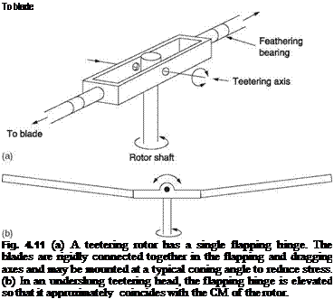 |
bearing is then raised above the feathering axes at the hub so that it is essentially at the rotor CM. There will then be less vibration when the tip path axis is not parallel with the shaft axis. The result is called an underslung rotor shown in Figure 4.11(b). As the rotor head itself tilts to stay in the plane of the rotor disc, the effect of Figure 4.5 cannot occur and so dragging hinges are not needed to overcome it. Forces due to varying drag in translational flight are resisted by blade stiffness.
The rigid connection between the blades means that their dragging frequency will be very high. It will be seen in section 4.17 that this means no drag dampers are required. The undercarriage needs no damping to prevent ground resonance and can be a simple tubular skid arrangement. This further reduces the weight of the machine.
Two-bladed rotors have a disadvantage that both of the blades simultaneously enter a lift trough in forward flight at 90° and 270° of rotation. This causes a twice-per- revolution hop (two-per) at the hull. Later teetering rotors incorporated a degree of flapping flexibility in the rotor head to decouple the hop from the hull. This is shown in section 4.20.
At speed the hull of a zero-offset machine tends to blow back because the drag D is applied a moment arm c below the suspension point as shown in Figure 4.12. At speed, the tail plane will have to apply a download T at moment arm b to counter the blowback. As a result the shaft and tip path axes nearly coincide. In a machine with an articulated or flexural head the hinge offset will generate a restoring couple if the hull is blown back so a less powerful tail plane is sufficient.
The main advantage of the zero-offset rotor head is that no moments can be transferred to the mast from the blades and so the mast can be very light. The absence of dragging
 |
and undercarriage dampers allows a further weight saving. However, it is vital that the machine is never placed in a flight condition where the rotor thrust is downwards, because in this negative-g situation the hull attitude is unstable, like a pencil balanced on its point.
In the worst case the hull can roll so that the limit of travel of the teetering or flapping hinge is reached. The side thrust from the tail rotor can initiate such a roll. The resultant pounding of the limit stops can break the mast. In zero or negative g the rotor will cone flat or downwards raising the possibility that if the hull pitches the tail boom can swing into the rotor disc.
A number of Robinson helicopters have been lost due to these effects, although the manufacturer stresses the avoidance of manoeuvres such as pushovers that can induce the negative-g condition. In the event of getting a zero-offset helicopter into negative g, there is only one solution and that is to return lift to the blades. This can be achieved by the application of back cyclic or raised collective or both.
In some zero-offset helicopters, such as the Bell 222, a strong spring is fitted to the teetering axis that minimizes the negative-g instability, but it does require a stronger mast and gearbox to withstand the spring forces.
Zero-offset heads will not tolerate a wide range of CM movement in any direction and are more prone to blade sailing when starting in high winds.
Different rotor head designs respond to cyclic control inputs in different ways contrasted in Figure 4.13.
Consider a two-bladed rotor where the pitch control rods are at 90° to the blades. For example, if the swashplate is tilted down at the front, the pitch angle of the blade moving forwards will be reduced, and the pitch angle of the opposite blade will be increased. This will cause a lift moment difference that results in a rolling couple. However, the gyroscope-like phase lag of the rotor will convert this into a pitch forward, so the front of the rotor disc will drop. In the hover, if the rotor is articulated, it will continue to pitch forward until it is parallel with the swashplate. At this point there will be no more
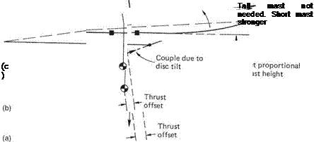 |
Fig. 4.13 Comparison of the response of zero-offset, offset and hingeless rotors to a cyclic input. (a) In the zero-offset head, a moment is produced because the rotor thrust no longer passes through the Cm. (b) In the offset head, the blade root tension is not symmetrical and a couple is produced in addition to the effect of (a). In a hingeless rotor head, (c) couples can be applied to the mast via the stiffness of the blades.
cyclic variation of the blade pitch angle, and so the rotor will remain at this angle. The tip path plane tries to stay parallel to the swashplate. This is known as following, and the speed with which the rotor follows the swashplate is known as the following rate.
The following rate depends on the relationship between the aerodynamic forces trying to tilt the disc and the inertial forces trying to oppose the tilt. The aeromechanical parameter that is used to quantify the phenomenon is called the Lock number.
For a given rotor, the following rate is proportional to the RPM and the air density. Operation at high density-altitude will result in the cyclic response reducing, and changing in phase.
In practice the following rate is generally high enough that the rotor will respond to a change of control axis within about a revolution. This does not mean that the whole machine will respond in this way, which is just as well. There is a considerable difference between the following rate and the response rate of the machine.
In a real helicopter, the rotor is not rigidly attached to the hull because of the presence of flapping hinges or flexures. As the rotor disc tilts, the hull will lag behind so that the tip path axis and the shaft axis do not coincide. This non-coincidence causes moments and it is these that govern the tilt of the hull. As the hull tilts, it causes a further tilt of the swashplate. This causes a further tilt of the rotor and so on. This is an example of positive feedback. Consequently in practice a steady application of cyclic control causes the rotor disc to tilt at constant speed. The ratio between the two is the response rate. The stiffer the connection between the rotor and the mast, the more the rotor is able to tilt the hull and swashplate, and so the greater is the positive feedback and the greater the response rate for a given cyclic application.
In general the stiffer the rotor head, the more rapid the response rate will be. Before the mechanism was understood, some experimental helicopters had response rates beyond the ability of the pilot and were uncontrollable. The use of hinged rotor heads in early helicopters had the advantage of reducing the response rate to what the pilot could manage.
The case of a machine that is initially hovering in equilibrium will be considered. In the zero-offset head, the application of a cyclic input causes the tip path plane to tilt with respect to the mast. As a result the thrust vector no longer passes through the CM, and a roll couple is created as shown in Figure 4.13(a). This will be proportional to the height of the rotor above the CM, and is a further reason for tall masts on teetering machines. The tip path plane initially tilts without the mast following it. Since the cyclic pitch control operates with respect to the mast axis, tip path tilt opposes the cyclic pitch control, so the further the disc tilts with respect to the mast, the less cyclic pitch change the blades get. Excessive following rate is thus prevented. As the teetering head cannot exert a couple on the mast, it can only pitch or roll the hull if the rotor thrust is tilted. If the rotor thrust is reduced for any reason, the cyclic control becomes less effective. This may happen in a pushover manoeuvre. The rotor disc will follow the cyclic control, but the hull doesn’t follow the disc. Such a situation may result in mast or droop stop pounding and all pilots who want to live will avoid it.
In the case of an articulated rotor head with offset flapping bearings, the tip path plane tilts as before, and moves the thrust vector with respect to the CM as before, but in addition the blade tensions no longer align and this results in a roll couple being applied to the rotor head as shown in Figure 4.13(b). The further apart the flapping bearings are, the more powerful this effect will be, speeding up the following rate.
Consider a fully articulated head with torsion springs fitted to the flapping and dragging axes. If the springs are stiff, there will be little deflection of the bearings. Deflection will be transferred to the blades and they will flex. If the springs are weak, there will be little to prevent deflection of the bearings, and bending loads on the blades are minimized. Clearly the flexural rotor head (c) can behave more or less like an articulated head depending on the stiffness of the flexures. The stiffness of the flexures may be different in the flapping and dragging directions. Sections 4.16 and 4.17 will explore the effects of dragging stiffness.
In the flexural rotor head, a single structural element often acts both as a bearing and as a spring. It will bend, but not without an applied moment, and so flapping and dragging are allowed by a combination of rotor head and blade flexing. The distribution of bending is clearly a function of the relative stiffness. All other things being equal, in an articulated head the flapping hinge offset determines the magnitude of the couple applied to the mast when the tip path axis deviates from the mast axis, whereas in a hingeless head this couple is determined by the stiffness of the system. In order to simplify analysis of the dynamics of a helicopter having a hingeless head, it is possible
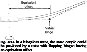 |
to describe the rotor by its effective or equivalent offset. Figure 4.14 shows that this is the radius of a virtual flapping hinge that would produce the same couple for the same disc tilt.
In the hingeless rotor head the tip path plane will attempt to tilt as the result of a cyclic control application, but the roll couple applied to the rotor head will depend on the flapping stiffness. Hingeless rotor machines with stiff flapping flexures can be highly manoeuvrable, as the Westland Lynx regularly demonstrates. In fact a hingeless rotor helicopter can be rigged to hover upside down as many model helicopter pilots have demonstrated.
Whilst the stiff hingeless rotor head leads to an agile machine, it will impose heavy bending loads on the blades and possibly also on the feathering bearings, which must be designed accordingly. Unless carefully designed, such rotors can also respond so rapidly to cyclic inputs that control is difficult. A permanently operating gyrostabilizer may be needed.
In hingeless rotors with stiff flapping flexures, the thrust vector offset with respect to the CM is much less important, and the mast does not need to be so tall, although machines with very short masts have suffered from powerful canopy vibration due to the non-uniform rotor downwash. Stiff rotors can withstand a wider range of CM travel because a rotor head couple can be used to keep the hull in the correct attitude, being limited by stresses in the mast and its bearings.
The stiff hingeless rotor is the goal for the ultimate in manoeuvrability, at the cost of a rougher ride and the need for a stronger mast and airframe. A more compliant hingeless rotor head allows a more cost effective solution and a better ride. The bearings of the articulated head are replaced by elements that can flex and thus need no lubrication or maintenance. It is not inconceivable that flexural heads will be developed which will last the life of the machine. Given the high maintenance costs of helicopters, any development that tangibly reduces wear and maintenance is highly significant.
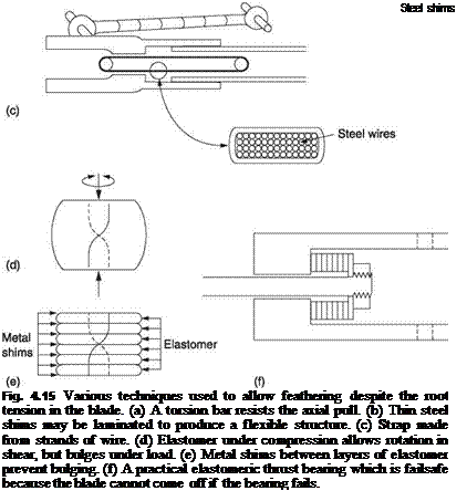
Despite the enormous pull of the blades, it must be possible to rotate them on their feathering axes in order to control the pitch angle. There are several approaches to the problem of the feathering bearing and these are contrasted in Figure 4.15.
Raoul Hafner first used a torsion bar shown at (a) to eliminate the axial thrust in the feathering bearing so that the remaining bearing became essentially a locating sleeve. It is a characteristic of bending and torsion that the greatest stress is caused at the surface
 |
so the interior of thick components is unstressed. This is why tubes are used instead of solid bars. A given cross-section of material will be more rugged if it is divided up into many slim elements in parallel and in addition will be easier to twist. This division into many elements also gives a degree of protection against failure because some elements can fail without the whole assembly failing.
The blade may be attached by laminated steel shims shown at (b) which can twist as the pitch is changed. PTFE tape may be placed between the shims to allow one to slide over the next. A variation in the idea is used by Bell on the JetRanger. Here the tensile element is a strap made from hundreds of strands of steel wire (c) like the cable in a suspension bridge. The blade is guided by a sleeve bearing that only takes bending loads.
Enstrom use an elastomer in compression to retain the blade. Elastomers are virtually incompressible but flexible synthetic compounds. Figure 4.15(d) shows that if a block of elastomer is placed under compressive stress, it will bulge at the sides. If the bulging is serious, the strength of the material will be exceeded and it will tear. Bulging would also allow the blades to move away from the mast, causing balance problems. Figure 4.15(e) shows that this problem is overcome by interleaving thin shims of metal with layers of elastomer. The metal shims prevent bulging under compression, but have little effect on the ability of the unit to twist so that pitch changes can be made. As the diagram shows at (f), the blade is guided by sleeve bearings, but the elastomer takes the thrust. Note that the system is failsafe because the bearing is in compression. Even if the bearing begins to disintegrate, the blade cannot come off.
In the Enstrom only the feathering axis is elastomeric. Aerospatiale pioneered a spherical elastomeric laminated bearing which allows full articulation in addition to feathering.
There are a number of mechanisms suitable for pitch control. No two designs have exactly the same control linkages, but the diagrams here are representative of actual practice. One of the best ways of appreciating how these systems work is to have someone move the controls of a helicopter one at a time whilst observing how the linkages move.
The most common control system is the sliding swashplate shown in Figure 4.16(a). The swashplate is made in two halves. The lower part is fitted with a spherical bearing so that the swashplate can tilt to any angle in any direction. The sphere can also slide up and down, often on the outside of the gearbox. A large diameter ball race is fitted between the two halves of the swashplate. A pair of jointed scissors links is fitted. One of these ensures that the lower half of the swashplate cannot revolve and the other ensures that the upper part turns with the rotor shaft. Each rotor blade grip is fitted with a pitch-operating arm. The end of each arm is connected to the periphery of the swashplate by a pushrod fitted with spherical bearings.
Movement of the collective lever raises or lowers the swashplate, and this causes all of the pitch operating arms to rotate all of the blades about their feathering axes by the same amount. In addition, movement of the cyclic stick in two axes causes the swashplate to tilt in two axes. Simultaneous lifting and tilting of the swashplate by two controls requires a device called a mixer, an example of which is shown in Figure 4.16(b). One end of the mixing lever is pivoted on the helicopter frame or on the gearbox and is connected to the collective lever by a rod. The opposite end is fitted with a bell crank operated by one axis of the cyclic control. The cyclic pitch changes take place differentially around the average pitch determined by the collective setting.
Figure 4.16(b) shows only one dimension of the cyclic mixing for clarity. In practice the cyclic control works in two axes and two bell cranks are fitted to the mixing lever. These bell cranks are connected to the swashplate by vertical rods and to the cyclic stick by horizontal rods. Moving the collective lever moves both bell cranks bodily up and down together, and so the swashplate rises and falls. Moving the cyclic stick rocks the bell cranks and tilts the swashplate about the collective setting in any desired direction.
Figure 4.17 shows an alternative arrangement known as a spider. The spider has radial spokes, one for each blade. Pushrods connect the ends of the spokes to the pitch operating arms. The hub of the spider is spherical so it can tilt and slide within the shaft and it is fitted with a vertical post passing down through the centre of the shaft
|
|
|
Fig. 4.16 The swashplate is a common method of controlling a rotor. (a) The two halves of the swashplate are connected by a ball bearing. (b) A mixer allows the swashplate to rise and fall with collective input whilst tilting with fore-and-aft cyclic inputs. |
and protruding below the gearbox. The lower end of the post is moved up and down to obtain collective pitch changes and from side to side in two axes to obtain cyclic pitch control. Figure 4.17 shows an installation in which the radial arms pass through slots in the rotor shaft. Such a system is used in the Lynx where a significant part of the control system is protected inside the rotor head. In the spider system, jointed rods approach the bottom end of the spider post in three axes, and tilt and lift the spider.
|
Rotorhead
Fig. 4.17 A spider installation in which vertical movement of the spider controls collective pitch, whereas tilting the spider applies cyclic pitch. In this example the arms of the spider emerge through slots in the rotor shaft. In some cases the spider emerges from the top of the rotor shaft. |
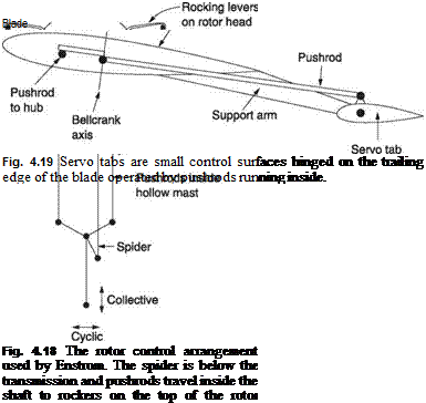
The Enstrom has a control linkage in which the pitch control rods pass up the centre of the rotor shaft to give an extremely neat external appearance and reduced drag. Figure 4.18 shows that the rotor head is fitted with rocker arms to transfer pushrod motion to the pitch operating arms. The pushrods are connected to a miniature spider located below the gearbox. The spider itself swivels on a universal joint so it can tilt in two axes whilst turning with the rotor. The spider support slides up and down in the rotor shaft under the control of a fork on the collective crank. The cyclic control rods tilt the spider to obtain cyclic pitch variation about the average collective setting.
Figure 4.19 shows the principle of servo tabs. Instead of attempting to change the blade pitch at the root, the blade is fitted with a small aerodynamic control surface rather like a miniature tail plane, typically at about 75% of rotor radius. Pushrods inside the blade allow the angle of the servo tab to be controlled. Servo tab systems have the advantage that the pilot only has to move the tab; the blade is moved by aerodynamic force on the tab. As a result power assistance is not necessary. The blade shank is made flexible to allow the tab to twist it. As the pitch control force is provided directly to the blade at an outboard location, there are structural and flutter resistance advantages. Servo tabs have been used extensively in the various models produced by Kaman, and are extremely effective. It is not clear why they have not been more popular elsewhere.
In a zero-offset rotor head such as the one shown in Figure 4.16, the rotor has a phase lag of 90° and to compensate, the pitch operating arms have an advance angle of 90°. In this case, the swashplate tilts in two axes exactly as the cyclic stick does and
 |
the axis about which the swashplate turns is the control axis. In fact the control cranks could be designed so that the swashplate stays parallel to the cyclic stick.
In multi-bladed heads this situation is seldom found. Such heads will be articulated or flexural and their flapping frequency will not be identical to the rotational frequency. As a result their phase lag will not be precisely 90° and the control system will need to compensate by arranging to tilt the swashplate in a slightly different direction to the cyclic stick.
Although an advance angle of 90° is easily obtained in a two-bladed teetering rotor, with articulated heads it becomes impossible because the end of the pitch-operating arm must terminate on the flapping axis to avoid the S3 effect (see Figure 4.9(b)). In multi-blade heads the end of the pitch-operating arm must remain clear of the next blade root. When the advance angle of the pitch operating arms is less than 90°, this is corrected by advancing the stationary part of the swashplate. Figure 4.20 shows that
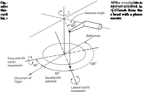
the pushrods from the cockpit must now connect at different angles. By consensus, all rotational angles are measured in degrees from the tail boom in the direction of rotation as shown.
The control axis can stay parallel to the cyclic stick, but the axis of the swashplate will tilt with a phase shift with respect to both. For example, a four-bladed head may have an advance angle of only 45°. The swashplate tilt will need to be advanced a further 45° with respect to the cyclic stick. Pushing the stick forward would cause the swashplate to tilt down midway between the front and the advancing side, i. e. at a phase angle of 135°, so the lowest point on the control orbit is reached 45° before the straight ahead position. At this point the pushrod going straight up to the pitch-operating arm will set the advancing blade at 90° to minimum pitch. The same blade will reach maximum pitch 180° later, and so there will be a roll couple towards the advancing side. The phase lag of the rotor will convert this to a forward tilt.
In other words the swashplate linkage has advanced the stick movement with respect to the control axis by 45°, the pitch-operating arms have advanced it a further 45°, and the 90° rotor lag cancels both, making the rotor tilt to follow the cyclic stick. Inspection of the cyclic pushrods in the Enstrom or the Lynx will show that they approach the spider at 45° either side of the centreline. The pitch-operating arms have an advance of a further 45°. The Chinook, having three-bladed heads, has an advance angle of 60°. In contrast the JetRanger, having only two blades, can have an advance angle of 90° in the pitch operating arms, and the swashplate moves parallel to the control axis. Since the advance angle of the pitch-operating arms and the phase advance of the
swashplate always add up to the phase lag of the rotor, they can generally be ignored for the purpose of studying rotor response, and all that is of interest is the control axis.
The direction of main rotor rotation is quite unimportant. On most American machines the blades rotate anticlockwise when viewed from above, whereas most French and Russian machines use the opposite rotation.
The controls of a fixed-wing aircraft tend to be blown to the neutral position by the slipstream, and this results in the pilot feeling resistance roughly proportional to control deflection. This feel is important so the pilot knows how much control power he is using. In the helicopter, there is no equivalent of feel in the cyclic control. Forces fed back to the cyclic stick from the rotor head bear little relationship to the deflection, so feel must be provided artificially. This is done by springs that tend to return the cyclic control to a central position.
The cyclic displacement needed in translational flight to counteract lift dissymmetry and inflow roll would be tiring to maintain against spring pressure, so a trim system is used to alter the neutral position of the springs. Figure 4.21 shows how a trim servo works. The trim servo has telescopic cylinders containing strong springs that normally
|
Fig. 4.21 A cyclic trim servo. (a) Springs 6 and 8 bias the stick to a neutral point which can be moved by an electric motor 1 which drives a worm 2, a wheel 3 and a leadscrew 4. If the pilot moves the stick away from the trim servo, sleeve 5 and rod 7 move together, compressing spring 6. In the opposite direction, spring 8 compresses and sleeve 5 remains stationary. (b) Circuit of trim motor drive. The motor direction is selected by choice of field coils which are wound in opposite senses. |
hold the telescopic elements at their end stops. Control movement will compress one or other of the springs to give feel. The neutral position of the springs can be adjusted by an electric motor operating a screw jack. One trim motor is fitted to each cyclic axis. The motors are controlled using a small four-way switch mounted on the cyclic stick where it can easily be reached by the pilot’s thumb. The switch is simply moved in the same direction the pilot is pulling the stick to hold the desired attitude. The force needed to hold the stick will be felt to reduce as the trim motor runs. Limit switches prevent the trim motor running too far and jamming.
As an alternative to trim motors, the centring springs may be attached to the hull reference by magnetic clutches. These are normally engaged by permanent magnets and the application of current in a coil can cause them to release. If the pilot holds the stick in the desired position and briefly applies the trim release current, the springs will extend to their neutral position and when the clutches grip again, the cyclic stick will be held in the trimmed attitude. The force trim release button will be on the handle of the cyclic stick.
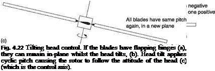 |
The equivalence of flapping and feathering was introduced in section 4.3. A rotor flapping with respect to the control axis is feathering with respect to the tip path axis. Figure 4.22 shows that this principle can be used for cyclic control. If the head has flapping hinges, it can be tilted with respect to the tip path axis. The result is that the blades are now cyclically feathered and the rotor will try to roll to a new attitude where the flapping and feathering cease. In the hover it will be able to do so, but in
 |
translational flight a steady application of cyclic feathering is required to overcome lift asymmetry.
Early de la Cierva autogyros had aircraft-style control surfaces and no rotor control at all. The rotor was equipped only with flapping hinges. In forward flight, lift asymmetry would result in extra lift on the advancing side, but this would precess to an aft tilt of the disc. Figure 1.10 showed that the thrust of the airscrew overcomes the rearward component of rotor thrust due to the aft tilt. As the attitude of the hull does not change when the rotor tilts aft, the mast is now tilted forwards with respect to the tip path plane. The result is that the rotor has cyclic pitch applied. In an autogyro of this kind the rotor will flap back until the correct amount of cyclic pitch is obtained for the airspeed. Whilst the autogyro flies in this way, it should be emphasized that the helicopter cannot and does not.
 |
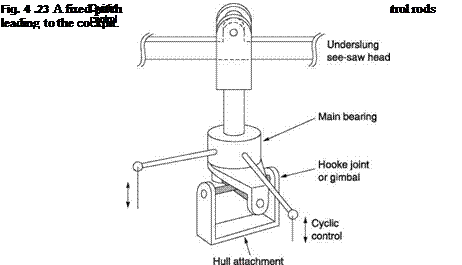
In later de la Cierva machines, the aircraft control surfaces were dispensed with and the pilot could tilt the rotor head for pitch and roll. This approach is used to this day for control of lightweight fixed-pitch autogyros. Where there is no shaft drive or collective control, the rotor head can be very simple, as shown in Figure 4.23. The rotor requires just a teetering hinge and the head is mounted on a gimbal so the pilot can tilt it. The tilting head can only apply cyclic pitch. Where collective control is required, a feathering bearing will be needed and so the tilting head has no advantage. Hafner was the first to build an autogyro with cyclic and collective control and the mechanical solutions he devised would be used in his subsequent and successful Sycamore helicopter.
In-plane blade motion is variously called ‘lead lag’, ‘lag’ or ‘dragging’. This author prefers the term dragging because lead lag is cumbersome and lag can be confused with phase lag; another thing altogether. Section 4.6 illustrated the mechanisms responsible for dragging. In many rotor designs, dragging hinges or flexible members are provided
|
Fig. 4.24 When a blade drags, the CM moves closer to the rotor axis. In rotating co-ordinates, centrifugal force creates a restoring moment proportional to deflection such that the blade has a resonant response to excitation in dragging. Unlike flapping, the aerodynamic damping is low. |
to reduce stress. In other designs, the rotor is designed to be extremely stiff, but as stiffness is always finite, there will still be some dragging motion. In all cases the dynamics of the system must be considered in order to avoid resonances.
In a traditional articulated rotor head, the dragging hinge cannot apply a restoring moment to the blade. The only restoring force for dragging motion in this case is due to rotation. Figure 4.24 shows that when a blade drags on a hinge having an offset from the rotor axis, the CM of the blade moves closer to that axis. When the rotor is turning, the CM will tend to be at the greatest possible radius and so if the blade drags forward or back, there will be a restoring force. Figure 4.24 is drawn in a rotating frame of reference in order to arrest the rotation. The acceleration of the blade is now zero and has been replaced by an equivalent centrifugal force. It will be seen that the centrifugal force, which must pass through the rotor axis, creates a small moment due to the drag hinge offset.
The restoring moment is proportional to the deflection and the result is that a blade which suffers an in-plane disturbance will tend to execute simple harmonic motion at its resonant frequency. In an articulated rotor, resonant frequency is proportional to the square root of the stiffness. The stiffness is due to centrifugal force and is proportional to the square of the RRPM. Thus the dragging resonant frequency will be proportional to RRPM as was the case for articulated flapping. However, unlike flapping, the only aerodynamic damping available to the dragging motion is due to changes of profile drag. Damping will often need to be augmented by mechanical means.
In hingeless rotors there will be some degree of structural stiffness that will provide a restoring force for the blade even when the rotor is not turning. The dragging resonant behaviour of a rotor can be characterized by the Southwell coefficients. Figure 4.25 shows how the ratio of dragging resonant frequency to rotor frequency is determined by K1 and K2. K1 reflects the resonant frequency when the rotor is not turning, as determined by the blade inertia and the stiffness of the rotor/head system in the dragging plane and is called the structural stiffening component. For an articulated head, K1 is zero because the dragging hinge has no stiffness. K2 is determined by the effective or actual dragging hinge offset and represents what is usually called the centrifugal stiffening component.
Figure 4.25(a) shows that in the articulated rotor, the hinge offset and consequent restoring forces are generally small and so the dragging resonant frequency is a small proportion of the rotor frequency, typically between 20 and 30%.
In a hingeless rotor, shown in Figure 4.25(b), at low RRPM the structural stiffness will dominate, whereas at high RRPM rotational forces dominate and the dragging
 |
 |
Fig. 4.25 Blade dragging is characterized by Southwell’s coefficients which describe the static and centrifugal components of the restoring force. (a) In the articulated rotor, there is no static stiffness. The dragging frequency is a fraction of the rotor frequency. (b) In the hingeless rotor there is static stiffness so there is a finite resonant frequency even at zero RRPM. As RRPM increases, centrifugal stiffening dominates and the frequency becomes asymptotic to what it would have been for a hinged blade with the same mass distribution.
frequency becomes asymptotic to what it would have been with no structural stiffness. As a result the dragging frequency is no longer proportional to RRPM.
It should be appreciated that in the above discussion and in Figures 4.24 and 4.25 the dragging frequency is with respect to the turning rotor, not with respect to stationary co-ordinates. Frequencies experienced at the hull will be in stationary co-ordinates and will be different from the frequency discussed here.
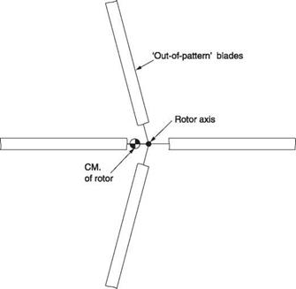
Given the flexible nature of rotors, it is possible for the centres of mass of the blades to get ‘out-of-pattern’ as shown in Figure 4.26. This is the term describing the condition where the blades are not evenly spaced around the disc. This may be due to an external influence such as the impact of a run-on landing or starting the rotor on a slope. It may also be self-excited.
Section 4.16 considered the resonant dragging motion of a single blade, whereas in practice it is necessary to consider the phase relationship from blade to blade. Figure 4.27 shows some possibilities for a three-bladed rotor. Rotors with more blades will also behave in the same way except that there are more phases of blade motion. Two – bladed rotors have different characteristics, but because such rotors seldom employ dragging hinges these differences will not be enlarged here.
It must be stressed that throughout Figure 4.27 the diagrams are in rotating co-ordinates so that the rotor appears to be stopped. Figure 4.27(a) shows the case where, for example, a sudden increase in drive torque has caused all of the blades to drag back by the same amount. They will all resonate in the same phase and the result is that the CM of the rotor is undisturbed. Figure 4.27(b) shows the case where there is a 120° phase difference between the motion of each blade. Now the centre of the rotor hub is moving in a circle. The motion may be visualized by considering the operation of a three-cylinder radial engine.
|
Fig. 4.26 Out-of-pattern blades shift the CM of the rotor and whirl the top of the mast. |
Figure 4.27(c) shows the same situation except that the phase relationship is -120°. The hub is still moving in a circle, but in the opposite direction. There is a strong analogy here with the three-phase electric motor that can be reversed by changing any two connections. This circular motion is known as whirling and it may be forward, in the same direction as the rotor, or backward, in the opposite sense to rotor direction. Figure 4.27(d) shows the case where one blade is not dragging, but the other two are dragging at 180°. Now the hub motion is linear.
If the effects of Figure 4.27 are considered in a non-rotating frame of reference, (a) will have no effect. Effect (b) causes circular whirling at a frequency which is the sum of the rotor frequency and the dragging resonant frequency, whereas (c) will result in circular whirling at a frequency which is given by the rotor frequency minus the dragging frequency. The whirling frequency seen by the hull has been modified by the addition of the rotor frequency. If the whirling experienced by the hull is in the same direction as the rotor turns, it is said to be progressive. If it is in the opposite sense it is said to be regressive. The whirling orbit is reminiscent of some types of food mixer. A mild form of such an orbit is usually experienced during rotor starting with an articulated rotor and is called ‘padding’ by pilots.
In a real helicopter these whirling forces are applied to the top of the mast. The CM of the hull is well below the rotor head, and the result is a combination of pitching and lateral rocking. The moment of inertia of a helicopter about the pitching axis is quite high owing to the long tail boom, but there is less inertia about the roll axis, so generally lateral movement will dominate. The hull will not be infinitely stiff and may also be supported on a sprung undercarriage, and so it will have natural resonant frequencies of rocking.
|
Fig. 4.27 Effects of dragging blade motion. (a) A sudden application of drive torque may result in all three blades dragging in the same phase. (b) When the dragging of each blade is at 120° phase to the next, the hub moves in a circle. (c) If the phase relationship of (b) is changed, the direction of whirling is reversed. (d) Where two blades drag in anti-phase and one blade is stationary, the hub is driven in a line. Note that all of these examples are in rotating co-ordinates. |
In the absence of preventive measures, if a resonant frequency in the hull is the same as that of a whirling frequency, one of two things can happen. Either the hull will act as a vibration absorber as was described in section 3.27, and the whirling will be opposed, or the rocking will become increasingly violent until the machine either comes apart or turns on its side. The phenomenon was first observed when a taxiing autogyro struck a rock with a wheel and literally disintegrated.
Needless to say this Jekyll and Hyde behaviour in seemingly similar circumstances means that the mechanism involved must be extremely subtle. Whilst the results of ground resonance are painfully obvious, the mechanism causing it is not obvious at all. Until a mathematical basis for the phenomenon was found, designers proceeded empirically. For example, Frank Piasecki obtained an improvement on his first machine by filling the tyres with cork. It was concluded early that ground resonance is purely a mechanical phenomenon and that aerodynamic forces are not significant. There are some parallels with whirling phenomena observed in other disciplines such as steam turbines.
The first full mathematical treatment of ground resonance was due to Robert Coleman and Arnold Feingold who were working at NACA (the forerunner of NASA). The mathematics turned out to be so complicated that the authors had to present their results in the form of charts intended to be practically useful without the reader needing to have advanced mathematical skills. Using these charts, designers were able to tame ground resonance, but this is not the same thing as understanding it. In order to understand ground resonance it is necessary to consider the geometry of whirling. Initially this will be considered for the case of the rotor alone.
The rotor is assumed to be isolated, and turning without translating. There is no external force on an isolated system so, according to Newton’s laws, the overall centre of mass of the rotor cannot move. If the centre of mass of the hub is whirling, this must mean that the blades together must have an effective centre of mass that is whirling in the opposite direction. Figure 4.28, which is in rotating co-ordinates, shows the orbits of various points on a blade and hub in a forwards whirling system. There will be a null point on the blade between the drag hinge and the blade CM that is oscillating radially but not tangentially. Note that the motion for a backwards whirling system can be seen by reversing all of the circles and ellipses.
In whirling, the KE of the hub is constantly changing because the circular motion requires a constant change of velocity. It follows that the kinetic energy of the blades must also be changing constantly. The blade KE variation is due to motion of the blade CM plus that due to in-plane rotation of the moment of inertia of the blade about the null point. Essentially whirling is a continuous interplay of blade and hub energy and in the absence of friction at the hinges and any aerodynamic effect it could continue indefinitely.
 |
Figure 4.29 is in stationary co-ordinates. Figure 4.29(a) shows an articulated rotor turning anticlockwise and whirling forwards whereas (b) shows the same rotor which is still turning anticlockwise but which is whirling backwards. Let these rotors be fitted to a helicopter having a rocking hull resonance. In both cases the figure shows the blade at
Fig. 4.28 In an isolated whirling rotor, the overall kinetic energy must remain constant. Consequently there must be an energy interchange between the blades and the hub. If the hub is whirling in one direction, the blade CMs must be whirling in the opposite direction. The loci of several points in the whirling system are shown.
|
Whirling at rotor Hull |
|
Fig. 4.29 (a) A rotor turning anticlockwise with forward whirling. The reaction from the hull opposes the whirling. (b) A rotor turning anticlockwise with backward whirling. The reaction from the hull which is the same as in (a) is now in the same direction as the whirling and amplifies it. This is the mechanism of ground resonance. |
180° passing over the nose. In the case of (a), to obtain the rocking frequency seen by the hull, the forward whirling frequency must be added to the rotor frequency. Clearly the whirling is progressive. If the hull/undercarriage system is resonant at this frequency, then it will produce a force opposing the rocking excitation because the response of the hull at resonance must be anti-phase to the exciting motion as was shown in section 3.27. This force is applied at the mast. It will be clear from Figure 4.29(a) that at the instant depicted by the figure, the angle в between hub and blade shank is increasing. The force applied by the mast tends to reduce в, thereby opposing the whirling. As a result, the system is stable. Ground resonance cannot occur due to the higher whirling frequency resulting from forward whirling.
In the case of Figure 4.29(b) the whirling is backward. To obtain the rocking frequency seen by the hull, the forward whirling frequency must be subtracted from the rotor frequency. However, the whirling frequency is lower than the rotor frequency, so the whirling seen by the hull is still progressive. If the hull has a rocking resonance at this frequency, it will produce a force in anti-phase to the whirling as before. However, it will be clear from Figure 4.29(b) that at the instant depicted by the figure, the angle в between hub and blade shank is decreasing. The force applied by the mast tends to decrease в further, thereby augmenting the whirling. As a result, the system is unstable. Ground resonance occurs due to the lower whirling frequency resulting from backward whirling.
In mechanical terms, the mechanical impedance of the system has become negative, so that it can gain energy from forces that would otherwise oppose motion. Negative impedance is used in electronics to construct oscillators. The criterion for this to happen is that the whirling must be both progressive and backwards. Given that the system is unstable in this mode, an undamped rotor can spontaneously display ground resonance.
In the absence of preventive measures, a helicopter on the ground with progressive backward rotor whirling is a mechanical oscillator. Given the huge amount of energy stored in the rotor, once started the whirling will increase in amplitude until something breaks. Hull rocking resonance can only occur if there is a reaction from the ground, hence the name of the phenomenon. This also explains why a machine can fly safely but disintegrate on landing, as has happened on a number of occasions.
There are a number of solutions to ground resonance which will be explored. It will be seen from a consideration of Figure 4.29 that damping any changes in the angle в will be highly effective hence the use of dragging dampers in the traditional fully articulated rotor head. In many cases damping is provided in the undercarriage to dissipate landing impacts and this damping can augment but not replace the damping in the head.
In modern helicopters employing damping, ground resonance is virtually unknown provided the dampers are kept in good order. These dampers may be hydraulic, similar to automobile dampers, which work by forcing oil through a small orifice, or elastomeric, which work by dissipating heat in hysteretic flexing. The latter have the advantage of needing no maintenance. Oil filled dampers will lose effectiveness if the oil leaks.
Given the destructive nature of ground resonance, it is a good idea to examine the dampers as part of the pre-flight inspection. By moving the blade on its dragging hinge, the resistance of the damper can be felt and the oil can be heard rushing through the damping orifice. All of the blades should feel and sound the same. If one blade feels different the damper may have some air in it. As the air is forced through the damping orifice the sound will change. Whilst one weak damper may not cause ground resonance, it may result in an increase in vibration in forward flight. It is also useful to learn the characteristics of the machine’s padding on start-up. If the rotor dampers are satisfactory, but there is unusual padding, the undercarriage oleos may need attention. A smoother rotor start may result if all of the blades are first moved to their rearward damper travel limit. Unusual padding may also result if the machine is parked on a slope when gravity will tend to take the blades out of pattern during the early stages of starting.
Figure 4.30 shows an interference diagram or Coleman diagram for an articulated rotor. K1 = 0 and the dragging frequency is small in relation to the rotor speed. Thus the rotor speed always overcomes the backward whirling and so all of the frequencies
|
Fig. 4.30 An interference diagram for an articulated rotor. The dragging frequencies fan out above and below the rotor frequency. Both are progressive but one is backward. |
concerned are positive. It was seen above that the dragging resonant frequency is proportional to rotor frequency. Thus as rotor frequency increases, the upper and lower whirling frequencies will be found symmetrically above and below rotor frequency. The horizontal line in the figure is the rocking resonant frequency of the hull. As such a rotor is started from rest, there will first be random padding due to the initial blade orientation. At a rotor frequency corresponding to point A, the upper whirling frequency coincides with the hull frequency. As the upper whirling coincidences are always stable, the hull acts as a vibration absorber and this will be noted as a lull in the padding. If the padding motion is noted, it will be seen to reverse phase after point A because the system has passed through a resonance.
Further increase in speed makes the rotor frequency coincide with the hull frequency at B. Only if there is any mechanical imbalance in the rotor (a defect) will there be any response. Further increase in rotor speed results in coincidence between the hull frequency and the lower (backwards) whirling frequency. This is the coincidence responsible for ground resonance and the dampers will be working to prevent it. The padding may be worse at this rotor speed. Flight RRPM will be above C where rotation should be smooth.
A ‘soft-in-plane’ rotor has no dragging hinges, but a relatively compliant blade root or hub so that there is a small restoring force even when the rotor is stationary. Consequently the dragging resonant frequency starts at a minimum value and increases with RRPM. Figure 4.31 shows that when this characteristic is added to the rotor frequency, the forward whirling is always progressive and the frequency increases from the static value to become asymptotic to the value determined by centrifugal stiffening. Points A and B are stable as for the articulated rotor. However, the backwards whirling frequency is initially higher than the rotor frequency. The whirling is actually in the opposite direction to the rotor and so is regressive. If this regressive whirling coincides with a hull frequency, the result is stable because the criterion for ground resonance is not met. In regressive backwards whirling the whirling is backwards in both rotating and stationary co-ordinates and the phase reversal needed for instability is absent.
However, when the rotor frequency in Figure 4.31 becomes equal to the backwards whirling frequency at C, the whirling frequency becomes zero. At any higher rotor frequency the rotor frequency exceeds the whirling frequency and the backwards whirling
|
Fig. 4.31 A soft-in-plane rotor has a regressive dragging region as far as point C at low RRPM, but this is not unstable. |
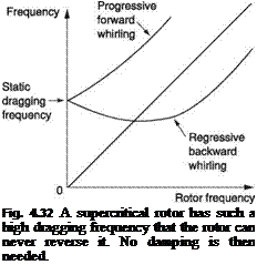 |
becomes progressive again. The frequency then rises to become asymptotic to the value determined by centrifugal stiffening. Point D in Figure 4.31 corresponds to a coincidence between a hull frequency and a progressive backwards whirling frequency, at which ground resonance can occur. Consequently soft-in-plane rotors still require damping.
A ‘stiff-in-plane’ or ‘supercritical’ rotor has a powerful dragging restoring force due to its construction and so has a significant dragging resonant frequency, even at rest. When the rotor is turning, the dragging frequency increases even further due to centrifugal stiffening. Figure 4.32 shows that, by definition, in the case of a ‘stiff-in-plane’ rotor, the whirling frequency is always higher than the rotor frequency. The behaviour of the forward whirling is benign as before. However, as the backwards whirling frequency is so high, the rotor frequency can never reverse it and so backwards whirling is always regressive in the case of a stiff-in-plane rotor. In that case the unstable combination of progressive backwards whirling can never occur and such a rotor can function with no damping at all. Two-bladed teetering rotors take advantage of this concept. They are built without dragging hinges to obtain supercritical dragging behaviour.
There is a small possibility of a damper failure and so it is as well to know how to handle it. There are two ways to recover from incipient ground resonance, depending on the rotor speed at the time it happens. If sufficient revs are available to permit flight, the answer is to take-off immediately. With no ground reaction against the undercarriage, the hull rocking resonance cannot occur and the shaking stops immediately. An attempt at a gentle landing may succeed, but if not then a landing should be attempted on a soft or high friction surface which is more likely to absorb energy than tarmac. It is important that there is no groundspeed whatsoever at the moment of touchdown. If insufficient rotor revs exist for flight, the solution is to change the frequency of the excitation away from the hull/undercarriage resonance. This may be done by reducing rotor speed by cutting the throttle and using the rotor brake if fitted.
 |
Air resonance is a condition primarily relevant to helicopters having hingeless rotors. In articulated rotors the natural frequency of the blade about the lagging hinge is low
and lag dampers are in any case present to prevent ground resonance. Furthermore the motion of the hull is decoupled to some extent by the articulation. In a hingeless rotor the blades lag by flexing and the stiffness is higher, leading to a higher natural frequency of lagging motion. The relatively stiff connection between the rotor and the hull means that large rotor moments can excite hull flexing. If such hull flexing is resonant then an unstable system could exist. A bending mode of the hull could result in a lateral motion at the rotor head that is similar to the rocking experienced in ground resonance.
It should be appreciated that resonance may also be excited by the tail rotor. This will be discussed in Chapter 5.
Dynamic rollover is a hazard that can only occur when a helicopter is in contact with the ground in some way. Normally the cyclic control has complete authority over the attitude of the helicopter, but interference from the ground or from external loads can reduce or even overcome the cyclic authority. Section 4.15 introduced the tilting hub mechanism for cyclic control. If the hull of a helicopter is forcibly tilted, the rotor will follow. Dynamic rollover occurs when external tilting forces overpower the cyclic control. Teetering or zero-offset rotors are more prone than offset or hingeless rotors because their cyclic authority is small to begin with.
Dynamic rollover becomes a possibility when the conditions on one side of the hull are different from those on the other side. This may be due to an attempt to land or take-off from a slope, an underslung load snagging a skid or a skid being stuck in mud or the surface tension of wet sand. Most winches for personnel recovery are fitted at one side of the machine and if a winch rope snags on the ground it can cause difficulty. A side wind and the thrust of the tail rotor complicate the matter.
Figure 4.33(a) shows what can happen with a stuck skid. The pilot raises the collective lever to lift off, but the stuck skid combines with the rotor thrust to produce a roll couple that could exceed the power of the cyclic control. In many cases the machine will be on its side before the pilot can react and the cyclic authority becomes academic. The roll accelerates because as the hull tips it increases the cyclic input to the rotor and causes further roll. A variation of this hazard is where the stuck skid suddenly comes free and the machine ends up on its other side because the pilot does not remove the lateral cyclic quickly enough.
Figure 4.33(b) shows a helicopter about to lift a slung load. Unknown to the pilot the load strap has snagged a skid. As the machine rises, once more the rotor thrust and the load strap tension create a couple on the hull and the dynamic rollover takes place. Most helicopter winches are installed with a view to bringing loads alongside one of the hull doors. The load is applied with a considerable moment arm from the machine CM. Moments due to normal loads can be resisted by the rotor, but in the event that the winch line became snagged an attempt to climb would result in dynamic rollover. This is one of the reasons why the pilot is provided with means to jettison loads in an emergency. Underslung loads can be jettisoned by releasing the load hook that may be electrically operated. Winches are fitted with cable cutters that may be explosively actuated.
Figure 4.33(c) shows an attempted landing on a slope. After the first skid has touched, the machine rotates about that skid. As it comes down, the control axis must be kept vertical by the application of cyclic control. The question is, what happens when the cyclic reaches the end of its travel and the other skid still is not in contact? The rotor disc cannot be kept horizontal and there is a danger of dynamic rollover. If the landing
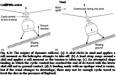 |
is continued, the hull will roll and carry the rotor with it due to the tilting head effect. When the downhill skid contacts, there may be enough roll momentum that the roll continues, with the uphill skid lifting. Once the CM of the machine is outside the skid base there is no recovery. This explanation is the origin of the slope landing limit laid down for each type of machine. These figures should be ignored at one’s peril.
Slope landings can be made harder or easier by wind. Figure 4.33(d) shows the wind blowing upslope. This is an advantage because more cyclic travel is available. However, if the wind subsequently reverses, it may become impossible to take-off because insufficient cyclic travel exists to tilt the disc into wind when the mast is tilted downwind. An experienced pilot might perform a ‘hop’ take-off which consists of bringing the rotor to flight RPM with neutral cyclic and then pulling collective rapidly to exit at a right angle to the slope. Once the gear is clear of the ground full cyclic authority becomes available.
The preferred technique in all external load handling or slope landing situations is to proceed very slowly, and if the cyclic travel approaches the limits the manoeuvre will have to be halted. This means in the event of attempting a take-off, rotor thrust should be applied very gradually so that any roll does not proceed too far. If anything goes wrong, the collective should be lowered. With the rotor thrust gone, the couple
disappears and the machine should fall back onto its gear. In the event of a sloping landing, if the cyclic stick travel is becoming extreme, the landing should be rejected. The collective lever is pulled up to get the uphill skid off the ground. Again the couple is eliminated because there is no ground reaction. Even if the roll has started, a smart and powerful application of collective will recover cyclic control as soon as the skid leaves the ground.
Rollover is also possible in a hingeless rotor machine if the cyclic control is not trimmed to neutral before collective is raised to take-off, although the mechanism is not the same as that of dynamic rollover. Pilots like to tilt the disc around on the ground to check the cyclic controls before flight. Hingeless rotor machines can have extremely high cyclic power without much rotor tilt being present. The amount of tilt that would be safe in an articulated machine might roll over a hingeless machine. Sometimes the undercarriage squat or ground contact switch may be used to limit cyclic authority when the machine is on the ground.
The number of approaches used in rotor head design over the years has been subject to wide variation. In the earliest days the theory of rotor dynamics was not well established and most designs mixed theory with empiricism. As understanding increased, attention turned first to optimization of design for a particular purpose and subsequently to such refinements as the reduction of vibration and of build and maintenance cost.
Figure 4.34 shows the evolution of zero-offset heads. These are usually underslung so that the hinge pin passes through the CM of the coned rotor. Supporting the rotor at its CM allows the blades to conserve momentum as the disc tilts and dragging hinges can be eliminated. This means that the rotor can be made supercritical in dragging. Ground resonance cannot occur and no damping is needed in the head or in the landing gear. This allows a cost and weight saving in small machines.
At (a) is the fully gimballed teetering head which essentially contains a Hooke joint so that the rotor can tilt in any direction with respect to the mast. The blade grips are mounted on feathering hinges. The feathering axis is parallel to one of the gimbal axes and the attitude of the hub in that axis would be indeterminate were it not for an equalizing linkage that makes the pitch of each blade equal with respect to the hub. This type of head was used on early Bell and Hiller machines.
At (b) is the later type of teetering head where only a flapping hinge is fitted and tilting in the other axis is accommodated by the feathering hinges. This type of head can be seen on the Bell 206 JetRanger. It is not obvious how this arrangement can act as a universal joint to allow the disc to tilt in any direction relative to the mast. The answer is that the feathering bearings are used to provide the additional degree of freedom. Figure 4.34(c) shows a helicopter with a teetering rotor hovering with an offset CM. The control axis and the tip path axis are vertical, but the shaft axis is not. As the rotor turns, the blades remain at a constant pitch relative to the tip path axis and the control axis, but need to turn in the feathering bearings to do so. Thus in this case it is the rotor head that is oscillating about the blade root and not vice versa.
The feathering bearings and the underslung teetering bearing act as a Hooke joint to allow shaft axis to be different to the tip path axis. The Hooke joint is not ideal because of the inclination of the feathering bearings at the coning angle, but for typical shaft/tip path relationships the discrepancy is small. The Hooke joint is not a constant velocity joint, and some torsional flexibility will be required in the transmission.
![]()

|
|
|
|
|
|
|
|
|
|
Teetering hinge on rotor CM |
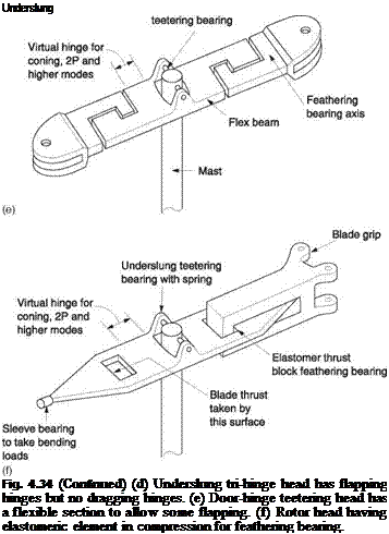
At (d) a variant of the teetering rotor is one in which the blades have individual flapping hinges so that no bending moments occur due to coning. This allows the blades to be more lightly built than in a conventional teetering system, and also reduces 2P hop. The effect of the offset between the flapping hinges is eliminated by the action of a third underslung bearing. This approach is known as a tri-hinge head and is used in the Robinson R-22.
At (e) is the so-called door-hinge hub. This hub is relatively thin in section to reduce drag. The thin section also introduces some flexibility to reduce the effect of two-per hop. This type of head was used on the Bell AH-1G.
At (f) is the semi-teetering head of the Bell 222. This contains elastomeric feathering bearings in compression, a thin flexural section for accommodating 2P hop and a centring spring on the teeter bearing to give stability in low-g manoeuvres.
Zero-offset heads are relatively intolerant of the CM location of the helicopter and cause handling difficulties in low-g conditions. The teetering hinge also allows blade sailing and starting the rotors may be impossible above a certain wind velocity because of the danger of a boom strike. This was acceptable in early machines, and possibly remains acceptable in today’s light machines, given the weight advantage due to the elimination of dampers. However, it is not acceptable in helicopters intended for military or emergency service. Other types of head can overcome these difficulties.
Although most zero-offset heads have two blades, more blades can be fitted. Figure 4.10 showed the zero-offset head of the Sikorsky R-5 that has three blades. As the flapping hinge axes pass through the mast axis no flapping moments can be communicated to the mast. However, the blades are individually hinged and no underslinging is possible. This means that the CM of the coned rotor is above the flapping bearings. When the disc tilts relative to the mast this arrangement cannot allow the blades to conserve momentum and dragging hinges must be fitted. This then requires drag dampers and landing gear damping. Such a head is a poor combination because it needs the drag hinge/damper complexity of the articulated head but does not offer the advantages.
In the classical articulated head the flapping bearings are offset from the mast axis so that a couple is exerted on the mast when the disc tilts, tending to make the hull follow the disc attitude. This couple may also be used to allow a non-ideal hull CM position. Any number of blades can be fitted in this way, usually between three and nine. When coned, the disc does not flap about its CM and so dragging hinges are needed. It was realized early that making the flapping and dragging hinges intersect allowed a conventional Hooke joint to act as flapping and dragging hinge. The feathering bearing was then placed outboard. This arrangement became relatively standard for a long time and appeared on rotor heads from numerous manufacturers including Sikorsky, Westland and Enstrom. The larger Mil machines place the dragging axis outboard of the flapping axis, probably to allow space for dragging dampers when a large number of blades are required.
The flapping blades need droop and sailing stops and sometimes these are centrifugally operated so that they only operate as the rotor slows down.
The articulated head results in a rotor that can start in higher winds than can a teetering rotor, and which can retain some control at zero g. On the other hand the articulated rotor is extremely complicated and needs a lot of maintenance. As materials have improved, it has become possible to build structures that will withstand stress without excessive weight or that will flex without fatigue. Thus instead of using a mechanical hinge to relieve the stress, the designer has the choice of withstanding the stress with a stiff structure or relieving it by flexing. With modern materials such as Kevlar and carbon fibre it is possible to make a rotor in which flexing is minimal. However, this is not desirable as a great deal of vibration would be transmitted to the hull and a very uncomfortable ride would result. Flapping blades act much like the suspension of an automobile and decouple the effects of gusts and alternating components of lift in forward flight. Another problem is that a perfectly rigid rotor would respond extremely quickly to cyclic inputs, possibly too quickly for a human pilot.
As a result the extremely stiff rotor is little used. Instead the goal is to make hingeless or bearingless rotors where vibration decoupling and stress relief are achieved not by an identifiable hinge, but by a low maintenance structure which is designed to flex. The term virtual hinge will be met to describe the existence of an axis about which flexing effectively takes place. Virtual flapping hinges decouple the non-constant lift in forward flight and virtual dragging hinges allow the blades to conserve momentum. The presence of the flexibility reduces bending stress in the blades and reduces the cyclic response rate of the rotor. It is also possible to incorporate the feathering hinge into the flexible structure.
The designer can choose an appropriate degree of flexibility depending on the role of the machine. For some military purposes, such as nap-of-the-earth flying, extreme manoeuvrability is required along with the requirement to sustain zero or negative g when cresting a hill at speed. This would suggest a rotor that is relatively stiff in flapping, which would also be able to start in almost any wind. Conversely a civil machine would benefit from a softer flapping flexure.
Dragging flexures are also subject to variations. If the dragging virtual hinge is made very stiff, the rotor can be made supercritical so that dragging dampers are not needed. However, stiff-in-plane rotors tend to produce more lateral vibration because the blades transmit the drag changes as they move between the advancing and retreating sides. As an alternative, the soft-in-plane rotor reduces vibration by allowing the blades to drag, but requiring drag damping to avoid ground resonance. The use of elastomeric damping will still allow a low maintenance structure. Clearly the dragging and flapping stiffness can advantageously be different and some ingenuity is required to provide suitable geometry.
Figure 4.35(a) shows the hingeless rotor head of the Bo-105. The only real bearings are for blade feathering. Flapping and dragging movements are accommodated through flexing of the blade shank. The dragging stiffness is supercritical and no dampers are needed. This is also a relatively stiff head in flapping, and pendulum vibration dampers are needed.
Figure 4.35(b) shows another stiff-in-plane head, that of the Lockheed AH-56 Cheyenne. This has door-hinge feathering bearings for low drag and a virtual flapping hinge. The flapping hinge is very stiff indeed and the following rate of the rotor is very high, requiring full-time gyro stabilization. This will be considered in detail in Chapter 7.
Figure 4.35(c) shows a soft-in-plane hingeless rotor from the Westland Lynx. Here the flapping flexure is a massive piece of titanium that is only flexible in the context of the enormous forces set up in a rotor head. The flexures are relatively stiff in flapping. Since the rotor can exert large moments on the hull, the Lynx does not need a tall mast; in fact it was a design goal to keep the height down to allow the machine to fit into transport aircraft, and a special low profile gearbox was designed to go with the rotor. With such a low rotor, the Lynx needs the tail boom to be angled down to give blade clearance before turning up to mount the tail rotor.
Figure 4.35(d) shows the head of the Bell 412. This has outboard dragging hinges and the drag damping is obtained by an elastomeric block acting on a inward extension of the blade grip which also mounts the pitch arms. The dragging hinges are mounted on flex beams that can twist to act as feathering bearings and bend to allow flapping. Two such flex beams are stacked to make a four-blade rotor.
Figure 4.35(e) shows a head developed by Aerospatiale. This uses a spherical laminated elastomeric bearing which takes the axial blade thrust whilst allowing feathering, flapping and dragging. Elastomeric blocks are fitted inside the blade grip and these couple with extension arms on the hub. The arms are stiff in the dragging plane, but the elastomeric block is in shear for dragging movements, giving a soft-in-plane characteristic and providing the drag damping. In flapping the blocks are in compression where they are quite stiff. Flapping flexibility is provided through a virtual hinge in the arms. The head arms also twist to allow feathering.
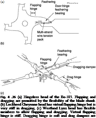 |
Figure 4.35(f) shows the head of the Bell 680. Pairs of blades are joined by long composite yokes that divide to pass clear of the mast. The yoke bends to allow flapping and dragging and twists to allow feathering. The yoke is long so that the strain due to feathering is moderate. The blade is attached at the end of the yoke, at some considerable radius from the mast. The blade is hollow at the root forming a cuff so that much of the yoke is inside the cuff. The inboard end of the cuff carries the pitch arm connected
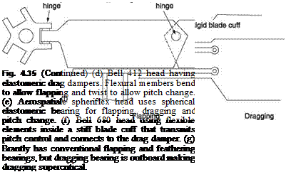
to the swashplate. When the blade drags back, the inboard end of the cuff will move forwards. Thus the drag damper is placed between the inboard end of the cuff and an arm attached to the mast. The hollow cuff approach gives a very clean head.
Figure 4.35(g) shows the rotor of the Brantly (now Hynes) helicopter. This has conventional offset flapping hinges, but the dragging hinges are placed part way down the blade. This large drag hinge offset makes the rotor supercritical and no dampers are required.
The rotor blade has an arduous life being subject to considerable and time-variant forces which in the early days made that life all too short. The construction of rotor blades has been the subject of numerous advances directed towards increasing blade life.
Early blades were built up rather like the wings of aircraft. Blades must have a certain weight both to store energy in the case of engine failure and to prevent an excessive coning angle. High torsional stiffness is also required. These requirements were initially met by building the blade around a steel tube. Collars were attached to the tube and these supported wooden ribs. A wooden leading edge was attached to the ribs and this would contain a metal insert to bring the mass centroid of the blade forward. The leading edge of the blade as far back as the spar might be covered with thin plywood. The whole was then covered with canvas and doped. Such construction lent itself readily to the incorporation of blade taper and twist. Machines having such blades had to be hangared because the blades were porous and moisture absorption could cause them to go out of balance. Such blades were of no use in tropical countries where the glues used could not withstand heat, humidity and bacterial/insect attack.
The solution was to make all-metal blades. Typically the leading third of the chord was a heavy D-shaped extrusion with the remainder of the chord made up of thin sheet metal, perhaps supported by aluminium honeycomb. Initially riveting was used; later advances in adhesives allowed bonded structures. Metal structures are subject to fatigue, particularly given the alternating loads experienced by the helicopter blade. In some blades a warning of cracks was given by pressurization of the blade and fitting a pressure indicator. In other cases the blade or spar was evacuated and a vacuum indicator was used instead. If the indicator reading was incorrect this might indicate an incipient crack or bonding failure. The use of extrusions made it difficult to incorporate blade taper.
As the military helicopter developed, consideration was given to resisting battle damage by designing redundant structures. In civilian applications a redundant structure can have a longer service life because a failure is not catastrophic. Redundant structures work by providing parallel paths for forces. In a rotor blade the single spar can be replaced by a series of smaller parallel box spars. The box sections may be of glass fibre which give support against buckling to steel spars between them. In some cases the spars can be made entirely of glass fibre, but it will usually be necessary to incorporate a metal strip bonded into the leading edge to give the correct mass centroid.
The trailing edge of the blade is relatively lightly loaded and it is advantageous if it is not too stiff in bending in comparison with the leading edge because this combination results in the blade washing out as it bends up; a stable condition. Generally a thin outer skin is used which is supported against buckling by a low density filling material such as alloy or composite honeycomb, foam plastic or end grain balsawood. In some machines the trailing edge skin is deliberately weakened by chord-wise slits that allow the blade stiffness to be defined by the spar. The trailing edge of the blade is a relatively non-critical structure and many machines have returned safely following substantial trailing edge damage.
As the conditions in which machines can operate are extended, it becomes necessary to protect against lightning strikes. The result of a strike is massive energy dissipation in any material presenting electrical resistance to the current path. The means of protection is to make the outside surface of the blades electrically conductive and to bond the blades together electrically. In this way potential differences across the rotor are minimized along with the damage.
Abrasion is also a fact of life for rotor blades. Hovering stirs up dust and grit and this can impact the leading edge of the blade. Composite blades may incorporate a thin metal anti-abrasion skin wrapped around the leading edge. In many cases a sacrificial coating made of self-adhesive tape is applied. This can be peeled off without damage to the blade and replaced.
Blade tracking is the process of adjustment that makes each blade fly identically. In the hover with the CM of the hull at the mast the blades should all have the same coning angle and the tips should all be in a single plane. If this is not the case there will not be a force balance at the hub and the result will be vibration. The tracking adjustment is performed by change to the length of the pushrod going to each blade pitch arm. The ball joints are attached to the pushrods with a screw thread to allow length adjustment.
It should be pointed out that a tracking adjustment can only succeed if the blades concerned are correctly statically and dynamically balanced. There may also be vibration if a piece of blade abrasion tape has come off or if the tape application on the blades is not identical.
The traditional way of measuring the tracking was to apply a different colour of chalk or greasepaint to each blade tip. A sheet of stout cloth on a frame was then brought carefully up to the edge of the spinning rotor so that coloured witness marks would be left on the cloth. If one blade were out of track it would leave a witness mark above or below the others. Clearly this method was not for the faint hearted and could only be done on the ground with the helicopter supporting some of its weight with the rotor.
Subsequently a system was devised in which inward facing coloured reflectors were temporarily fixed to the blade tips. These were illuminated by a strobe light triggered by a sensor on the mast so that as each blade passed the same azimuth angle the strobe light would flash. The machine could be flown with the apparatus attached and if the tracking was incorrect the reflectors would appear at different heights. Clearly the machine would have to be shut down each time an adjustment was required. Some helicopters have motorized adjustments that allow the pitch rod to change its length in flight. The optimum adjustment may be obtained by adjusting to minimize vibrations at some specified operating condition.
In some machines trim tabs are fitted to the trailing edge of the blades, which can be used to compensate for the effect of slight differences between the blades in forward flight.
The blades of a helicopter may take up a great deal of room and in some applications, such as operation from ships, folding blades will be needed as a practical matter. In a small machine this may be achieved entirely manually after first removing the locking pins. However, in large helicopters manual folding is not viable and a power – operated system will be needed. Figure 4.36 shows the blade folding system of the Sea King. In this five-bladed machine, one blade is positioned over the tail boom and does not fold. Blade folding can only take place if the rotor head is turned to exactly the correct angle. After the rotor has stopped, an hydraulic motor will turn the rotor to the correct angle and the shaft will then be locked.

|
|||
|
|||
|
|||
|
|
||
|
|||
|
|||
|
|||
|
|||
|
|||
|
|||
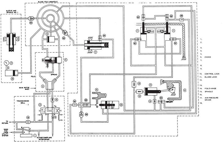

Fig. 4.36 Blade folding mechanism of the Sea King. See text.
There are some additional complexities involved in blade folding. First, folding the blade will put the blade centre of mass a long way from the feathering axis and the resulting couple could damage the swashplate and controls. This is prevented by a mechanism that locks the feathering bearings. Second, motion of the lead-lag hinges can interfere with the folding and it is necessary to position the lag hinges correctly. The lag dampers are also hydraulic rams.
Hydraulic pressure is supplied to the rotor head through a rotating seal. Initially, the lag hinges are positioned by applying pressure to the dampers. The dampers carry limit valves to allow fluid to flow once they have reached the end of their travel. This fluid flow operates the feathering bearing locks. The feathering bearing lock pins operate further limit valves to allow fluid to flow to the folding mechanism proper.
Locking pins in the hinges will then be withdrawn by hydraulic power. The retraction of the lock pins operates sequence valves which then apply fluid pressure to the bladefolding rams inside the rotor head. These drive sector gears in order to turn the hinges through the large angles needed. The hinge axes are not vertical, so that the blades fold back and down alongside the hull.
As the folding mechanism is self-sequencing, unfolding the blades is achieved simply by reversing the direction of hydraulic pressure on the rams. The folding rams retract to swing the blades out, and limit valves then apply pressure to the lock pin rams, which lock the folding hinges. Limit valves on the lock pins then allow pressure to the feathering bearing locks in order to release the pins. When the feathering lock pins retract, further limit valves allow flow to reposition the lag dampers.
For obvious safety reasons, the hydraulic interlocks ensure that the sequence cannot complete if any stage fails to operate. As a further precaution, the positions of the major elements are monitored by switch to operate a cockpit warning if any part is out of sequence.
Blade folding mechanisms are inevitably complex. In certain versions of the Osprey, not only do the blades fold parallel to the wing, but the wing also rotates 90° to align with the hull. Blade folding is expensive, adds weight and increases maintenance and will only be used where it is absolutely essential.
Reference
1 Gessow, A. and Myers, G. (1951) Aerodynamics of the Helicopter. Ungar, New York.
5


