Acceleration autopilot
Highly agile air-to-air missiles rely on tight autopilot control for successful target intercept. Because they zero miss distance by lateral acceleration, you will find that all modern missiles are controlled by acceleration controllers. To improve performance, an inner rate loop is added for stability augmentation. Both acceleration and body-rate feedback are provided by the accelerometer and rate sensors of the INS.
Airplanes are less likely to be controlled by acceleration autopilots because passenger comfort is more important than maneuverability. However, for special
applications, like unmanned combat air vehicles or cruise missiles, the normal load factor plane may contain an acceleration feedback loop. Such guidance systems as terrain following and obstacle avoidance or target homing require rapid response that only an acceleration autopilot can provide.
Having used classical control for the rate and roll autopilots, I use modern pole placement techniques for designing the acceleration tracking loops. For best performance, proportional and integral (PI) techniques are applied—proportional control for quick response and integral control for zeroing steady-state errors. After a general introduction to state variable pole placement techniques, I will deal with the pitch plane acceleration autopilot and solve for the three feedback gains that satisfy the specified closed-loop response. For missiles the yaw plane implementation is the same.
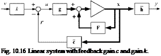
Let us formulate the problem (see Fig. 10.16). Given is the linear time-variant plant* = F(t)x +g(t)u. What is the controller gain c in order for the closed-loop poles to take their places at the locations pt, і = 1,…,« for all times t; and what is the gain к so that the steady-state gain is one? We consider only SISO systems, with v as input and у as output.
The solution follows the same steps we used for the rate loop, except now we employ the state variable form. The closed-loop system is * = [F(t) — g(t)c]x + kg(t)v with the closed-loop fundamental matrix [F(t)—g{t) c], whose eigenvalues must be equal to the desired closed-loop poles. Therefore, the condition for pole placement is
П
DetjIs – F{t)+g(t)c = ]~[(s – Pi) (Ю.76)
;=i
with n the number of states.
The forward gain is calculated on the basis that у = v when steady state has been reached, which is the case when * = 0. Employing the steady-state closed-loop system equation and the output relationship у = hx, we can solve for the forward gain
![]()
 |
1
h[F(t) – g(t)c]-lg(t)
Equation (10.76) is evaluated by equating terms of equal power in 5. This process leads to a system of linear equations, which can be solved for the controller gain c
c = P~’d (10.78)
where P is an n x n matrix and d an n x 1 vector.
For implementation, either in a simulation or onboard a flight vehicle, Eqs. (10.77) and (10.78) are calculated on-line, given the F(t) matrix and g(t) vector. Note that in general two matrix inversions of order n must be carried out. Fortunately, for the acceleration autopilot we can solve Eq. (10.78) algebraically, whereas later on the flight-path-angle autopilot of Sec. 10.2.2.6 requires the full matrix inversion. To adapt the controller gains to highly variable flight conditions, the desired closed-loop poles pt can be made a function of some flight parameter, say, time, dynamic pressure, or altitude.
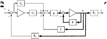
Let us get specific with the acceleration autopilot. Fig. 10.17 portrays the structure. The proportional and integral feedforward branches with their respective gains Gp and G/ are clearly visible. The major feedback loop is via the rate and acceleration gains c — k], A second acceleration feedback with unit gain
is wrapped around the outside to improve performance. We derive from this schematic the relationship for the control variable
и — — cx + G[ j(v — h%x)dt + Gp(v — h^x)
Then we augment the states by introducing the scalar auxiliary variable § = f(v— h$x) dt with its state equation
I = v — x
Substituting и into the open-loop system yields the closed-loop system, augmented by the auxiliary variable §:
![]()
 |
(10.79)
which we abbreviate by the equation
x’ = F'(t)x’ + g'(t)v
The eigenvalues of this closed-loop fundamental matrix F’ must be equal to the
desired closed-loop poles. The condition for pole placement is
Det[/s – F'(t)] = [](s – Pl)
i=i
|
П(* – л) (10-8°) 1=1 |
and specifically
The evaluation of this equation leads to the on-line calculation of the gains c, G and Gp, given the desired closed-loop poles pi.
 |
|
Now we are ready to design the acceleration autopilot for agile missiles. From Chapter 7 we carry over the linearized plant Eq. (7.69). It is similar to the rate equation, except for the angle of attack, which is replaced by the normal acceleration a:
To solve Eq. (10.80), we first establish the following correspondences with the plant equations:
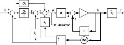
и = S; = [ 0 1]; c = [k.2 k]
 |
Then we apply them to Fig. 10.17 and display them in Fig. 10.18. Recognize the two acceleration feedback loops, the inner rate loop, and the two PI feedforward branches. The rate and acceleration signals are taken from the INS, and the <5
signal is sent to the pitch actuator. The gains k, k2, Gi are calculated from the pole placement condition Eq. (10.80)
|
k2Ms |
(ki + Gp)Mg |
G1M5 |
|
|
0 |
0 |
0 |
Because of the simple structure, it was possible to solve for the gains without a matrix inversion. The position feedforward gain GP is not accessible to the pole placement technique. It must be determined based on a root locus analysis.
In a typical application the dimensioned aerodynamic derivatives are loaded into the missile computer as tables of Mach and angle of attack; the velocity is available from the onboard INS. If the missile experiences little change in dynamic pressure, it may be sufficient to specify fixed closed-loop poles. However, in the case of widely changing flight conditions, the closed-loop poles are scheduled as a function of dynamic pressure. As a rule, it is sufficient to schedule the natural frequency w„ only while keeping the damping £ and the real pole p location fixed. The gain GP is usually fixed and apportions additional feedforward for increased speed of response.
As you check out your design, make sure that the gains are not too high and cause the control to saturate prematurely. Lowering the bandwidth con can alleviate a potential problem. For tetragonal missiles you can use the same acceleration loop for both the pitch and yaw planes. A roll position controller will round out your autopilot design. You will find such an example in CADAC SRAAM6, Module C2 Subroutines C2PI and C2ROLL.


