Aerodynamic controls
The most widely used method to control endo-atmospheric vehicles is through aerodynamic surfaces. By deflecting them, moments are generated about the c. m., which in turn rotate the airframe. The resulting incidence angles generate aerodynamic forces, which accelerate the vehicle in the desired direction.
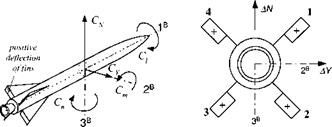
We start with the description of missiles, followed by aircraft. Figure 10.20 displays the positive sense of the aerodynamic moments and the convention of positive
|
viewed from the rear |
surface deflections. There are only three moments, rolling С/, pitching Cm, and yawing C„, but four surfaces to produce them. Therefore, the four surface deflections 51, 52, 53, and 54 are combined to compute three apparent controls, called roll Sp, pitch Sq, and yaw Sr:
Sp = i(—51 – 52 + 53 + 54)
5^ = 1(51 + 52 + 53 + 54) (10.85)
Sr = ±(-51 + 52 – 53 + 54)
A fourth relationship does not result in a moment, but only in a pure axial force:
Sd = 1(51 – 52 – 53 + 54)
By the way, the proposal has been made to exploit this drag force for retarding a reentry missile.
Unfortunately, no consensus exists concerning the positive sense of control surfaces for missiles. We follow here the recommendation of the former North American Aviation Corporation. Another convention defines the surface deflections as positive when they contribute to a positive rolling moment. Our approach (see the following equations) has the advantage that it agrees with aircraft conventions for positive control deflections.
Roll:
+Sp —»■ + AC; rolling moment
Pitch:
+Sq —»• +AC, v normal force
Yaw:
+5r —► +ДСу side force
Positive roll control (aileron) produces a positive rolling moment; positive pitch control (elevator) generates a positive normal force (but a negative pitching moment); and positive yaw control (rudder) creates a positive side force (but a negative yawing moment).
The missile autopilot sends the roll, pitch, and yaw commands to the actuators. Yet, before they can be utilized, they have to be separated into individual fin commands:
51 = —Sp + Sq — Sr
52 ![]() = —Sp + Sq + Sr
= —Sp + Sq + Sr
53 = +Sp + Sq — Sr
54 = +5/? + Sq + Sr
then each actuator module can convert the fin command Sic into an actual surface
deflection Si, where і = 1,2, 3. 4. We represent the response of the fin actuator
|
by a second-order transfer function
Si{s) _ col__________
8ic(s) s2 + 2i;cons + со2
with natural frequency con and damping t,. Although the transfer function models only the linearized dynamics, we include two important nonlinearities as portrayed in Fig. 10.21. DLMIX limits the deflection of the fin, and DDLMIX restricts the maximum fin rate. Limiting the fin rate should not be neglected because it can become the source of serious performance degradation.
This actuator facsimile is the standard model of the CADAC six-DoF simulations. Its implementation calls for careful coding of the limiting feature of the derivative 8i. For details you can consult the CADAC SRAAM6 simulation, Module C4.
 |
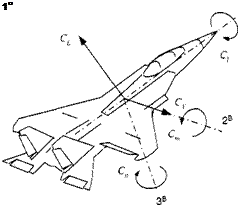
The same model is also used for aircraft-type vehicles, like cruise missiles, hypersonic vehicles, and, of course, the FALCON6. Some simplifications however apply. The basic control surfaces of aircraft are aileron 8a, elevator 8e, and rudder 8r. Autopilot commands can be fed directly to the surface actuators. Their positive directions are shown in Fig. 10.22. Aircraft control conventions, like those in the following equations, are similar to missile control.
Aileron:
+Sa —»• +ДС/ rolling moment
Elevator:
+Se —>■ +ACl lift force
Rudder:
+Sr -* +ACy side force
Again, only the aileron deflection produces a positive rolling moment. Elevator and rudder cause negative moments, while their positive sense is defined by the positive forces they produce.
For programming purposes we can copy the code of missiles, as represented by Fig. 10.21, and insert it into our aircraft simulation. I have done so for the CADAC GHAME6 simulation, Module C4.
Aerodynamic surfaces are sometimes inadequate to control the vehicle. Greater agility may be required of a missile. A hypersonic vehicle can reach such heights that, despite its velocity, the dynamic pressure has fallen below acceptable values. For these applications thrust vector control could be the solution.


