AFTTC method
This method was developed in the early seventies at Edwards AFB, and involved the aircraft performing consecutive turns through a common airmass. It was dubbed the ‘cloverleaf’ method due to the pattern the aircraft described in the sky. The aircraft flew three passes at 120° apart from each other at the same indicated airspeed. Although pre-dating the first method by some margin it fell out of favour in its original form as it required radar tracking which resulted in it being expensive and difficult to co-ordinate from the ground. However, with the advent of GPS, this method has now become much more economical. Recently Olson [7.8] re-introduced the method and presented a non-linear mathematical solution that removes the need to fly orthogonal headings.
7.3.2 Data presentation
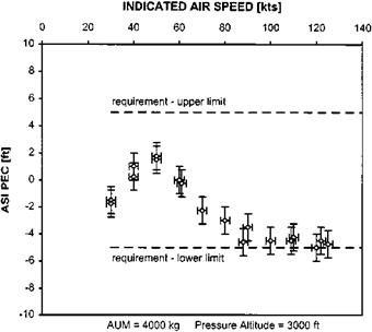
Test results are reduced and presented in the form of IAS against altitude or airspeed pressure error correction (PEC) and it is this correction that must be added to the
|
Fig. 7.4 Altimeter PEC data (obtained using the trailing pitot-static method). |
indication to yield the calibrated value. Level, climbing and autorotative flight PECs are normally presented on one graph for one aircraft configuration. Airspeed indicator PECs with sideslip are normally plotted in the form of PEC against sideslip angle for specific flight conditions (airspeed and power) for one aircraft configuration. Figures
2.4 and 7.5 show test data obtained for a medium sized twin engine helicopter and compares it with the specification requirements.


