Cockpit Simulator
The cockpit simulator encompasses all of the elements displayed in Fig. 11.1. The fledgling pilot is subjected to a complete palette of the sensory feedback: visual, vestibular (balance of the inner ear), somatosensory (seat-of-the-pants), and aural (acoustic). If these features are well integrated, the simulator will pass FAA Level D certification, authorizing its use for all flight training without air time. The airlines train their pilots in cockpit simulators, and the military services make use of specialized trainers. For instance, the V-22 Osprey trainer satisfies very demanding requirements and complies with Level D certification.
11.1.2.1 Vision system. Our eyes are a marvelous creation. Collaborating with the brain, they are able to process information unequaled by any computer. Their specification or I should say their physiology reads as follows: field-of-view for stereoscopic vision, horizontal ±70 deg, vertical ±50 deg; eye movement, ± 10 deg at 500 deg/s; head movement, ±100 deg at 10 to 100 deg/s; and resolution in the central region of the retina, 1 arc min (0.3 mrad). These characteristics must be matched by the vision system. It should be stereoscopic, with large field-of-view, high resolution and fast response.
 |
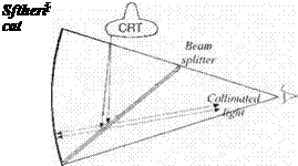
Not all of these requirements can be realized. Fortunately, stereoscopic pictures are not mandatory because the scenes are far removed. However, with close-up CRT screens, the impression of distant scenes must be created by collimating the light that enters the two eyes. Figure 11.2 shows the principle. The beam from the CRT is reflected off the beam splitter, to be returned by the parabolic mirror
|
Fig. 11.3 Generation of visual scene. |
through the beam splitter into the eye as collimated beams. The eye perceives the scene to be at infinity. A typical value for the horizontal field-of-view is ±48 deg and vertically ±36 deg. The refresh rate should be at least 30 frames per second to be flicker-free.
The scenes themselves derive from video tape or digital imagery. Figure 11.3 depicts the process. The position and attitude of the aircraft and the perspective of the pilot’s eyes are correlated with the three-dimensional visual database. A geometry processor projects the selected portion onto the two-dimensional plane and sends the polygons to the video display.
Many of the scenes are computer generated. However, for best effects, photographic pictures are used. You may even find photographic objects superimposed on a digital terrain database. Scene generation is the most computer-intensive part of a simulator. Its realism is a direct function of the invested computer power.


