Managing pressure errors
The Royal Navy developed one method of compensating for the deficiencies of airspeed indicators at low airspeeds. When Westland Lynx helicopters were taking off from ships’ decks it was observed that the pilot did not have reliable airspeed indications until the aircraft had achieved in excess of 40 KIAS. This was due to a combination of the low dynamic pressure itself and the downwash of the main rotor at high power settings. Consequently the pilot had no reliable means of judging when the helicopter had reached an airspeed from which it would be able to perform a flyaway in the event of an engine failure since the minimum speed for the flyaway was typically below 40 kts. The solution to this problem was to determine the relationship between airspeed and time when flying a standard take-off technique. This then allowed pilots to use time rather than airspeed to determine at which point a flyaway should be made rather than ditching conducted. The pilot was provided with charts that accounted for aircraft weight, OAT, height above water, and windspeed thus producing a critical time, known as Tcrit. Provided that the aircraft had passed Tcrit and the total
|
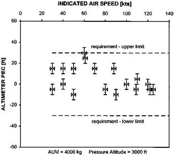
Fig. 7.5 Airspeed indicator PEC data (obtained using the trailing pitot-static method). |
intervention time did not exceed two seconds, then pilots were assured of being able to fly away with a minimum separation of ten feet from the surface.
Another area of the flight envelope where PEs can have a major influence is during instrument approaches. When involved in a precision approach, such as a GCA, the pilot is told the decision height (DH) for the runway he intends to approach. To this figure he may need to add the helicopter type allowance (see below) and a further increment depending on his instrument rating. In the UK it is usual to reduce the DH reported by the air-traffic controller by 50 ft. This takes account of the fact that the helicopter can transition to a lower speed, ultimately the hover, rather than having to perform an ‘S’ manoeuvre to align with the runway centreline before touching down. In the UK the minimum is 150 ft for a CAT 1 approach (a FW minimum of 200 ft reduced by 50 ft). This minimum may also be considered as being made up of a height to avoid obstacles, the dominant obstacle allowance, and a factor to account for both errors in the pitot-static system and the anticipated height loss involved in a missed – approach procedure, the aircraft allowance. Work done some 25 years ago [7.9] identified that for medium to large twin-engined helicopters using a 3° glide slope the aircraft allowance (AA) was typically 100 ft. This allowance was the summation of a number of factors and error sources associated with the static pressure system that feeds the altimeter. One source was the maximum permissible variation in the PEs across a fleet of similarly equipped aircraft.
The actual PEs associated with a particular model of rotorcraft in descending flight are dealt with separately in the helicopter type allowance (HTA). Although the runway DH plus the instrument rating factor is usually reported back to the GCA controller the effect of the HTA remains within the cockpit. Thus the HTA represents the increment in pressure height required to ensure that the true pressure height at the decision point does not fall below the minimum allowed. The HTA is determined by measuring the altimeter PEs whilst performing a GCA profile, typically 80 to 100 kts with a 500 ft/min RoD. This basic PE is increased by a factor to account for the stiction and lag in the instrument associated with responding to a steadily increasing static pressure, provided these errors have not already been included in the AA.


