Seeker kinematics
The main parts of an IR seeker are shown in Fig. 10.34. The optics, supported by the inner pitch gimbal, carries the focal plane array and is isolated from the support by the roll gimbal. To cool the detectors, the bottle contains pressurized nitrogen, which, when vented, cools and supplies the 70-80 К operating environment. The base of the sensor houses the electronics for the gimbals and the processor of the optical data. For an air-to-air application, the image processing can include target classification, aimpoint selection, and flare rejection. The main output of the sensor is the inertial LOS rate—target relative to the missile—expressed by the angular velocity vector of the LOS frame relative to the inertial frame.
Let us assail the coordinate transformations first. The mechanical roll and pitch gimbals orient the seeker head and its optics to the body frame. The associated head coordinates have their 1H axis aligned parallel to the optical axis and their 2H axis with the gimbal pitch axis. As you would expect, the seeker roll axis coincides with the body 1B axis. We build the transformation matrix [T]HB starting with the body axis, transforming it first through the roll gimbal angle фнв, and then through the pitch gimbal angle Qhb to reach the head axes, i. e.,
j// |яв_] Фнв_^в
 |
 |
||
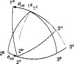
Figure 10.35 should help you visualize the two transformation angles. You can spot the two centerlines of the seeker and the missile, Iя and Is, respectively, separated by the angle вНв■ The gimbal transformation matrix (TM) is
|
Notice the difference of this roll/pitch TM and that of the pitch/yaw gimbals, Eq. (9.83). Both represent mechanizations with different limitations. The pitch/yaw implementation is limited in yaw to less than 90 deg—typically 63 deg—because of mechanical constraints. Our roll/pitch gimbal arrangement does not suffer these constraints, but has a singularity straight ahead, when the sensor points in the forward direction at any roll angle.
Because of this singularity, the processor implements a virtual gimbal transformation, using the standard sequence of yaw and pitch (azimuth and elevation) from body coordinates to the so-called pointing coordinates. We have met this sequence several times. Please refer to Sec. 3.2.2 and in particular to Eq. (3.25) for details. The sequence of transformations is from body coordinates through the yaw angle 1f/рв
 |
 |
 |
||
and the pitch angle 9рв to the pointing coordinates, i. e., ]p. Its TM is
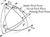 |
To compare the three coordinate systems, Fig. 10.36 delineates the body, head, and pointing axes with the angles of transformation, фНв, 9нв, and фнв, 9нв – You need to distinguish three different pitch planes. First, start with the missile pitch plane, subtended by Is and 3s, and roll through фнв to the seeker pitch plane Iя,
|
Fig. 10.37 Spherical triangle and focal plane. |
3й; second, start again with the missile pitch plane, but now yaw through іДрв to reach the pointing pitch plane lp, 3P.
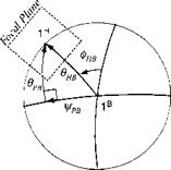
It is particularly informative to look down the nose of the missile and study the spherical triangle (Fig. 10.37) that encompasses the angles of both transformations. In it we see both the centerline of the missile 1B and that of the seeker head 1H. By Napier’s rule we can relate the pitch gimbal angle внв to the virtual gimbal angles
фрв, 9pb
внв = arccos(cos 9pB cos іДрв) (10.119)
as well as the roll gimbal angle
/ sin фрВ
Фнв = arctanl -—— ) (10.120)
V tan Орв )
When фрв = 0, then фив = 0; and when внв = 0, then фнв = 90 deg. Can you visualize the focal plane array centered and perpendicular to Iя?
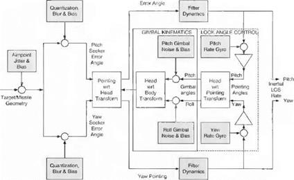
10.2.6.2 Seeker model. Having conquered the kinematics of the seeker, we can dig deeper and develop the mathematical seeker model. I shall break it into little bites as I have done before with the seeker in Sec. 9.2.5. But first, let us take the bird’s eye view of Fig. 10.38.
An IR seeker has two major functions: imaging and tracking. They are indicated by the bar on bottom of Fig. 10.38. The detectors of the focal plane array record the target image. By processing the gray shades of the image, the aimpoint is selected and its dislocation in the focal plane recorded as the error angle.
To be realistic, we have to include in our model some of the main error sources. They are identified in Fig. 10.38 by the shaded blocks. At the detector level a dynamic phenomenon called jitter can destabilize the image, and biases can be introduced by the optics. The finite number of elements affects the processing of the pitch and yaw error angles, and processing of the data introduces biases.
The tracking loop of the seeker consists of the mechanical gimbals, the LOS rate estimator, and several computational transformations. Some of the mechanical errors we consider are gimbal noise and biases and the instrument errors of
|
|
the rate gyros. The dominant time lags are caused by the filtering of the LOS signals.
Let us follow the signal flow from left to right in Fig. 10.38. The model begins with the true missile-to-target geometry s bt■ Corrupting the target by jitter and bias creates the actual missile-to-aimpoint displacement Sab in head coordinates. Then the displacement is converted into pitch and yaw error angles and again diluted by quantization, blur, and bias uncertainties. Now the signals enter the computergenerated world of pointing coordinates and, after filtering, produce the inertial LOS rates in pointing coordinates as seeker output.
With the output generated, you may think that the seeker description is complete. But the all important seeker feedback loop still needs our attention. Through this loop the LOS rates, referred to the inertial frame, are transferred to the body frame by subtracting out the body rates. Then the pointing angles are converted into gimbal angle commands, which, after the gimbal noise and bias are added, establish the transformation matrix of the head to the pointing coordinates [T]HB. At this point the tracker loop is closed, and the transformation matrix [T]HB is available for converting the error angles from head to pointing axes.
After this overview let us explore the seeker model in detail. Again, we start at the left side of the schematic and discuss first the aimpoint model shown in Fig. 10.39. The true displacement vector of the missile c. m. В wrt the target centroid T is given by the simulation in local-level coordinates [s^r]1. It is transformed to the head axes and converted to the actual aimpoint [5дв]я by introducing the displacement vector [5дг]я that models the corruption of the true target point T by jitter and bias
[Тдв]Я = [5дг]Я — [^вг]Я
I lumped these errors together into the displacement vector [5дг]я and applied Gaussian noise and bias distributions to randomize the effects. Seeker specialists do not like such a top-level representation of a very complicated imaging process. Yet, if you are building a system simulation, you have to treat each subsystem with equal emphasis and have to compromise fidelity. Through cajoling, you may be able to convince your seeker expert to distill the imaging errors into this random vector [5дт-]Я.
 |
The displacement on the focal plane is now converted into angles (see Fig. 10.40) and split into pitch and yaw error angle eY and eZ, respectively. At this point we
|
|
introduce the processing errors of quantization, blur, and bias, which you have to extract from the seeker’s specification. I use random draws from a Gaussian distribution in radians to model their stochastic nature. The output of the image processor is sHY and sHZ.
Let us have a closer look at the focal plane in Fig. 10.41. Its center is the point H, which is also the piercing point of the Iя axis (see Fig. 10.37). The 2H and 3я axes complete the head coordinate system. On the focal plane is also located the aimpoint A, as determined by the image processor. The true displacement error, expressed in radians, is composed of the two error angles
[єШ_Iя = [0 sHZ -eHY] (10.121)
With perfect gimbals and processing this displacement would be the desired LOS rate output of the seeker. However, the tracker loop introduces additional errors caused by the rate gyros, the virtual gimbals (pointing axes), and the mechanical
3P
gimbals. Therefore, through the feedback loops the pointing axis 1p is displaced from the center of the focal plane 1H. The actual displacement, available for output processing, is the distance between the aimpoint A and the piercing point P of the 1p axis [eAPh. Our next task is to model this displacement.
The triangle of the three points A-H-P in Fig. 10.41 relates the measured value of [єАР]н to the true displacement [єАН]н and the pointing error [єРН]н
[єАР h = [є AH]H – [єРН] h (10.122)
The є should remind us that the values are small and expressed in radians. Although the true value is given by Eq. (10.121), the pointing error, which is a function of the mechanical and virtual gimbals, still needs derivation.
The two transformations. Eqs. (10.117) and (10.118). are combined to form the pointing to head coordinate transformation
[T]PH = T]PB[T]HB (10.123)
Now here comes the juggling! Associated with the pointing axis 1p and the head axis 1H are the unit vectors
ГрйҐ = [1 0 0] [7Г7]" = [1 0 0]
Their tip displacement is the pointing error
[єРН]н = [T]PH[Pl]p – [Іц]н (10.124)
If the two gimbal transformations were perfect, [T]PH would be unity and the pointing error vanished. With Eqs. (10.121) and (10.124) substituted into Eq. (10.122), we have succeeded in modeling the measured aimpoint displacement on the focal plane array.
We transition now to the tracking loop by converting to pointing coordinates
[eAE]p = [T]ph[eAP]h (10.125)
and separating the measurements into pitch and yaw pointing error angles
ePY = —(eAP)p and ePZ — —{єАР)р
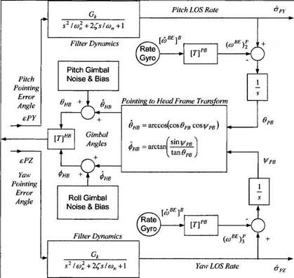
These angle errors are the input to the tracker loops. In Fig. 10.42 1 give you the entire tracking model so that you can follow in one graph the filtering, the body-rate compensation, the pointing angle generation, conversion to gimbal angle commands, and the gimbal mechanization.
The filters smooth the imaging and processing noise that come with the error angles before the LOS rates are sent out to the guidance computer. Flowever, the filtering causes time delays of the output signals. In effect, they are the dominant lags of the seeker. We use second-order transfer functions to model either a simple bandwidth filter or a sophisticated Kalman filter.
The output of the inertial LOS rates in pitch and yaw, ару and ri>z, respectively, are also the starting point of the feedback loops. Body rates from the INS rate gyros are converted to pointing coordinates and subtracted from the inertial LOS rates to establish the body-referenced LOS rates. Their integration leads to
|
Fig. 10.42 Tracker loop. |
the virtual gimbal angles фрв, врв, which are transformed by Eqs. (10.119) and (10.120) into the controls фнв, &нв of the mechanical gimbals. I have elected not to model the gimbal dynamics explicitly. State-of-the art technology delivers highly accurate mechanical devices, whose bandwidth is significantly wider than the filter response. Therefore, I account only for random noise and biases in the roll and pitch gimbals. The actual gimbal angles are фнв, бнв■ They determine the orientation of the focal plane array relative to the body frame, which is expressed mathematically by the transformation matrix
The tracker loop is now complete. The TM [T],m is combined with the pointing transformation [T]PB according to Eq. (10.123) to form the pointing wrt head TM [T]PH, which is used to convert the seeker error angles from head to pointing coordinates [see Eq. (10.125)].
Thanks for staying with me through this tour de force. You have mastered a difficult modeling task of a modern IR seeker, applying geometric, kinematic, and dynamic tools. The conversion to code is fairly easy with the provided equations. Yet, if you prefer, you can also use the code in the CADAC SRAAM6 simulation, Module S1. It is fully integrated into the short-range air-to-air missile. Its input file provides you with typical seeker parameters that you can use as a starting point for your simulation.
With this highlight we conclude the section of subsystem modeling of six-DoF simulations. You should have a good grasp of aerodynamics, autopilots, actuators, INS, guidance, and seekers. Supplemented by relevant material from the five-DoF discussion (Sec. 7.2), you should be able to model aircraft and missiles with six – DoF fidelity. If you need more detail, you can consult the experts. Assuredly, there are many more components of aerospace vehicles that we were unable to address. Unfortunately, the open literature is of little help. You will find contractor reports a proficient source of information, provided you can get access to them.
I hope you gained an appreciation of the modeling of aerospace systems. The best way to become proficient is for you to develop your own simulations. But first learn by example. Most of the examples I used have their counterpart in the software provided on the CADAC CD. I referred to them at the end of each section.
One more topic needs elaboration, which so far I have just alluded to: stochastic error sources for GPS, INS, seekers, and sensors and their effect on the performance of aerospace vehicles. With your curiosity aroused let us discuss these chance events.


