Simulations
The best way to learn the secrets of six-DoF simulations is by taking apart some well-written prototypes. In the early 1970s, when I was stranded at the White Sands Missile Range in New Mexico, 1 used the time to dissect my first missile six-DoF simulation. It was the spark that ignited the CADAC blaze.
There are a few good six-DoF simulations on the open market. If you can get your hands on one, study it diligently and learn by example. Here, I will describe briefly three prototypes based on the CADAC architecture. They have been mentioned throughout this chapter, and now the time has come to introduce them formally. The code is provided on the CADAC C D for your scrutiny.
9 G2 В G3 (ё A2 oo А1
 л>
л>
■Є АЗ З D1 R D2
10.4.1 FALCON6
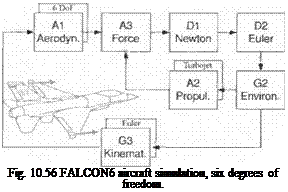
Let us start with a simple model. It is based on the description by Stevens and Lewis9 and the NASA database.34 Figure 10.56 depicts the seven essential modules of a six-DoF simulation: Newton’s and Euler’s equations with the aerodynamic and propulsive forces and the kinematic calculations. I will briefly describe each module.
For the Dl Newton Module the translational equations of motions [Eq. (10.3)] are solved with the flat-Earth assumption.
For the D2 Euler Module the rotational equations of motion [Eq. (10.18)] are tailored for aircraft with a cross product of inertia term. The angular momentum of the turbojet engine is also included.
For the G3 Kinematics Module the incidence angles a and /5 are calculated. The Euler angle rates are integrated to obtain the direction cosine matrix.
For the G2 Environment Module the ISO 62 standard atmosphere is implemented.
The AI Aerodynamics Module is patterned after Eqs. (10.61) and (10.62), but restricted to 0.6 Mach or lower.
For the A2 Propulsion Module the turbojet model of Sec. 9.2.2 applies here also. It calculates the thrust as a function of throttle setting, altitude, and Mach. It also includes a lag filter to model the spooling time delay.
The A3 Force Module combines the aerodynamic forces and moments with the turbojet thrust and readies them for the Newton and Euler equations.
The simulation does not have any controls. When you make a run, you may encounter an unstable region, and the trajectory will be cut short. I recommend you build your own autopilot, either by following Stevens and Lewis9 or working Problem 10.2.
10.4.2 GHAME6
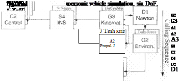
Here we meet again the NASA GHAME that we employed in Chapter 8. Now it has fully blossomed into a six-DoF simulation with elliptical rotating Earth and a full suite of autopilot options. Figure 10.57 shows the modules and their special features. For a summary of the essential kinematic and dynamic equations, see Fig. 10.6.
 |
For the Dl Newton Module the translational equations of motion are formulated in inertial coordinates [see Eqs. (10.42) and (10.43)]. Vehicle position is converted to longitude, latitude, and altitude and velocity to geographic coordinates.
For the D2 Eider Module the rotational equations of motion (10.44) are expressed in body coordinates.
For the G3 Kinematics Module the incidence angles a and /І are calculated and the direction cosine matrix integrated from Eq. (10.47).
For the G2 Environmental Module the standard atmosphere ARDC1959 is implemented. Options are provided for tabular atmosphere and winds. The turbulence model of Sec. 10.3.3 is also coded.
For the AI Aerodynamics Module hypersonic aerodynamics are modeled according to Eqs. (10.65) and (10.66) and are based on NASA data.15
For the A2 Propulsion Module the combined cycle engine of Sec. 8.2.4 is modeled, consisting of a turbojet, ramjet, and scramjet phase. An autothrottle controls thrust to maintain constant dynamic pressure.
For the A3 Force Module the aerodynamic forces, moments, and propulsive forces are combined and expressed in body coordinates.
For the S4 INS Module the space-stabilized INS of Sec. 10.2.4 is implemented. Gyro, accelerometer, and gravitational perturbations are accounted for.
The C2 Control Module offers a variety of controllers: roll control, SAS, pitch acceleration controller, altitude hold, and both heading and flight-path-angle hold autopilots. Refer to Sec. 10.2.2 for a detailed description. All autopilot modes have aeroadaptive gains, derived by the pole placement techniques.
For the C4 Actuator Module second-order actuators with rate and position limiters control the elevons and rudder. See Sec. 10.2.3 for details.
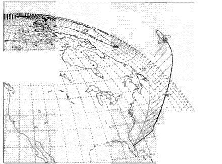
The CADAC CD has several test cases that you should exercise. Some results of the input file 1NCLIMB. ASC are displayed in Figs. 10.58 and 10.59. The run starts 3000 m above Cape Canaveral at a speed of Mach 0.75. Both the heading and flight-path-angle autopilots are engaged, and the autothrottle is set for 50 kPa dynamic pressure. After the climb-out at 20 and then 10 deg, the vehicle cruises at 30 km altitude until after 500 s it starts another shallow limb at 0.6 deg to top out at 40 km.
With the FALCON6 and GHAME6 code you have two simulations that cover the flight regimes of any aircraft over flat and elliptical Earth. Their aerodynamics

is a function of the angles a and /3. We round out our collection by a missile simulation with polar incidence angles a’ and ф’.


