SRAAM6
 |
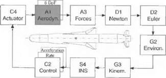
The SRAAM6 simulation models a generic short-range air-to-air missile. We encountered its five-DoF version already in Chapter 9. Now I present you with the flat-Earth, six-DoF benchmark version. By looking at the modules of Fig. 10.60, you can appreciate the complexity of this simulation. With nearly 6000 lines of FORTRAN code, it is the largest of all CADAC models. Actually, some of the modules are almost identical to the SRAAM5 versions. They are those forming
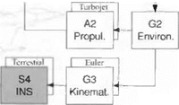
the navigation and guidance loop: Gl, SI, S2, S4, and Cl. Even the G2 and A2 modules can be adopted with minor modifications. However, the kinematic and dynamic modules are new and reflect the six-DoF implementation. They are summarized in Fig. 10.1. Let us briefly discuss the individual modules.
For the Gl Target Module target engagement scenarios are implemented. They are known by special designations, like Pre-Merge (shooter centered), One Circle Fight, Two Circle Fight, Lufbery Circle, Target Centered Engagement, Chase Circle, Head-On Circle, and Twin Circle. You just need to set the flag MINIT and invoke the preprogrammed initial conditions for the target and the shooter aircraft.
For the G2 Environmental Module the ISO 62 standard atmosphere provides pressure, density, and temperature.
For the G3 Kinematics Module the incidence angles a’ and ф’ are calculated, and the quaternion methodology of Secs. 4.3.3 and 10.1.1 is employed to obtain the direction cosine matrix.
For the SI Seeker Module imaging IR sensors are the current state of the art of short-range air-to-air missiles. Although only generic data are used, the roll/pitch gimbals and the coordinate systems are quite realistic. You can find the description of the seeker in Sec. 10.2.6.
The S2 Air Intercept Radar is a simple kinematic model of an acquisition and tracking radar, located in the shooter aircraft. It acquires and tracks the target and transmits that information to the missile at launch and during an optional midcourse phase.
The S4 INS Module is used in midcourse only. The nine error state equations (three positions, three velocities, and three tilts) bring realism to the fly-out accuracy. The derivation of the error equations is given in Sec. 10.2.4.
For the Cl Guidance Module a midcourse and terminal guidance phase is provided. In midcourse a simple pro-nav law is implemented, whereas the terminal phase relies on the compensated pro-nav law of Sec. 10.2.5.
For the C2 Control Module, during separation from the launcher, only rate damping is provided. Thereafter, the proportional/integral autopilot of Sec. 10.2.2.4 provides rapid response to the guidance signals.
For the C4 Actuator Module four second-order actuators with rate and position limiters control the four fins. See Sec. 10.2.3.1 for details.
For the A1 Aerodynamics Module the aerodynamics are patterned after Eqs. (10.69) and (10.70). The coefficients are expressed in tables as functions of Mach and total angle of attack, for power on/off, and variable c. m. locations. The length of the missile is 2.95 m, and its diameter 0.1524 m.
For the A2 Propulsion Module the thrust of a single-pulse rocket motor is given as a table of thrust vs time with backpressure corrections. Vehicle mass, c. m., and MOI are updated. Launch mass is 91.7 kg, and the motor fuel is 35.3 kg.
The A3 Forces Module converts the aerodynamic coefficients to force and moment vectors in body coordinates and adjoins the thrust component.
For the D1 Newton Module the translational equations of motion are formulated in body coordinates [see Eqs. (10.3) and (10.6)].
For the D2 Euler Module the rotational equations of motion (10.16) are solved in body coordinates.
For the G4 Impact Module the miss distance is calculated in the intercept plane. Figure 10.54 shows the details of a Monte Carlo run.
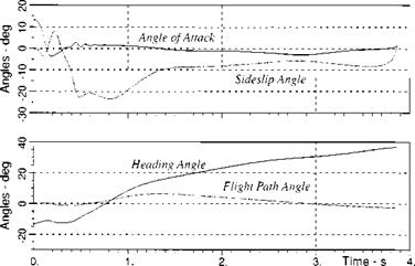
A typical engagement is shown in Fig. 10.61. With the shooter and target aircraft at the same altitude, the missile executes primarily a lateral maneuver, expressed by large excursions of the sideslip and heading angles.
|
|
My mammoth chapter has come to an end. I did not expect you to study it line by line. Your professional specialization may have drawn you to the aerodynamic models, the autopilot implementations, the guidance laws, or the seeker mechanization. Some of you may have gone straight for the examples. Whatever your interest, you probably griped that your specialty is not adequately represented.
For you novices, unburdened by years of experience, I hope you sensed a certain awe of the multidisciplinary challenge a six-DoF simulation poses. Learn by following in the tracks of others. Study the provided examples or other simulations and work the projects at the end of this chapter. Soon you will be the expert that others will consult in the pursuit of the perfect aerospace vehicle simulation.
References
‘Rolfe, J. M., and Staples, K. J., Flight Simulation, Cambridge Univ. Press, Cambridge, England, U. K., 1986.
2Zipfel, Peter H., “On Flight Dynamics of Magnus Rotors,” U. S. Army Technical Rept. 117, available at DTIC, ADA 716 345, Nov. 1970.
3“Department of Defense World Geodetic System 1984, Its Definition and Relationships with Local Geodetic Systems,” 3rd ed., NIMA WGS 84 Update Committee, NIMA TR 8350.2, Bethesda, MD, 4 July 1997.
4Torge, W., Geodesy, An Introduction, Walter de Gruyter and Co., Berlin, 1980.
5Britting, K. R., Inertial Navigation System Analysis, Wiley-Interscience, New York, 1971.
6AMTEC Corp., “Endo-Atmospheric Non-Nuclear Kill Simulation (ENDOSIM),” U. S. Army Strategic Defense Command, TR1158, TR1163, TR1161, Huntsville, AL, Aug. 1989.
’Jordan, W. E., “Simulation Models and Baseline Guidance and Control for Indirect-Fire Missiles with Strap-Down Inertial Guidance,” U. S. Army Missile Command, TR GR-76-41, Huntsville, AL, Jan. 1976.
8Savage, P. G., “Strapdown System Algorithms,” AGARD Lecture Series, No. 133, May 1984, p. 379.
9Stevens, B. L., and Lewis, F. L., Aircraft Control and Simulation, Wiley, New York, 1992, Eq. (1.3-6).
wLanchester, F. W., Aerodonetics, A Constable and Co., London, 1908.
11 Nielsen, J. N., Missile Aerodynamics, McGraw-Hill, New York, 1960.
l2Gentry, A. E., et al., “The Mark IV Supersonic-Hypersonic Arbitrary-Body Programs,” Air Force Flight Dynamics Lab., TR-73-159, Wright-Patterson AFB, OH, Nov. 1973.
13Williams, J. E., et al., “Missile Aerodynamic Design Method (MADM),” Air Force Wright Aeronautical Lab., TR-3109, Feb. 1988.
l4Magnus, A. E., and Epton, M. A., “PAN-AIR—A Computer Program for Predicting Subsonic or Supersonic Linear Potential Flows About Arbitrary Configurations Using a Higher Order Panel Method,” NASA CR-3251, Aug. 1982.
l5White, D. A., and Sofge, D. A. (ed.) Handbook of Intelligent Control, Van Nostrand Reinhold, New York, 1992, Chap. 11.
16Roskam, J., Airplane Flight Dynamics and Automatic Flight Controls, Vol. 1, Roskam Aviation and Engineering Corp., Lawrence, KS, 1979.
l7Britting, K. R., Inertial Navigation Systems Analysis, Wiley-Interscience, New York, 1971.
l8Widnall, W. S., and Grundy, P. A., “Intertial Navigation System Error Models,” Inter- metrics Rept. TR-03-73, May 1973, available from DTIC, AD 912 489L, Alexandria, VA,
l9Chatfield, A. C., Fundamentals of High Accuracy Inertial Navigation, Progress in Astronautics and Aeronautics, Vol. 174, AIAA, Reston, VA, 1997.
20Biezad, D. J., Integrated Navigation and Guidance Systems, AIAA Education Series, AIAA, Reston, VA, 1999.
2,Maybeck, P. S., Stochastic Models, Estimation, and Control, Vol. 1, Academic Press, New York, 1979.
22Stengel, R. F„ Stochastic Optimal Control, Wiley, New York, 1986.
23Hammersley, J. M., and Handscomb, D. C., Monte Carlo Method, Methuen and Co., London, 1964, reprint 1975.
24Zarchan, P, “Comparison of Statistical Digital Simulation Methods,” Guidance and Control Systems Simulation and Validation Techniques, AGARDograph No. 273, AGARD, 1988.
25Gelb, A., Applied Optimal Estimation, MIT Press, Cambridge, MA, 1974.
26Maybeck, P. S., Stochastic Models, Estimation and Control, Vol. 1, Academic Press, New York, 1979.
27Stengel, R. F., Optimal Control and Estimation, Dover, New York, 1994.
28Handbook of Geophysics and the Space Environment, U. S. Air Force Geophysics Lab., National Technical Information Center, ADA 16700, DTIC, Alexandria, VA, 1985.
29Von Karman, T, and Howarth, L., “On the Statistical Theory of Isotropic Turbulence,” Proceedings of the Royal Society of London A, Vol. 164, 1938, pp. 192-215.
3HDryden, H. L., “A Review of the Statistical Theory of Turbulence," Quarterly of Applied Mathematics, Vol. 1, 1943, pp. 7-42.
“Lumley, J. L., and Panowsky, H. A., The Structure of Atmospheric Turbulence, Wiley, New York, 1964.
■“Pritchard, F. E., et al., “Spectral and Exceedance Probability Models of Atmospheric Turbulence for Use in Aircraft Design and Operation,” U. S. Air Force Flight Dynamics Lab., Rept. AFFDL-TR-65F-122, Wright Patterson AFB, OH, Nov. 1965.
“Maybeck, P. S., Stochastic Models, Estimation, and Control, Academic Press, New York, 1979, p. 188.
“Nguyen, J. T., et al., “Simulator Study of Stall/Post-Stall Characteristics of a Fighter Airplane with Relaxed Longitudinal Static Stability,” NASA T. P. 1538, Dec. 1979.
Problems
10.1 GHAME6 flight control evaluation. The hypersonic NASA vehicle GHAME, modeled in GHAME6, has several control modes. You are to check out the dynamics of the open-loop and closed-loop response.
Task 1: Download from the CADAC CD the GHAME6 simulation and run
the test case INCLIMB. ASC. Try to maximize the terminal energy (altitude and velocity) at 1540 s flight time by modifying the trajectory profile. Plot your final trajectory (altitude, inertial velocity, Mach number, flight-path angle vs time) and record the end conditions of at least five trials in a table.
Task 2: Run GHAME6 without autopilot. Build the input file INOPEN. ASC
with the following modules: G2, ENVIRONMENT; G3, KINEMATICS; Al, AERODYNAMICS; A2, PROPULSION; A3, FORCES; D2, EULER; and Dl, NEWTON. With initial BALT = 15 km, DVBE = 720 m/s, and autothrottle set at 50 kPa, trim elevator DELEX to keep the vehicle with ±1000 m for 20 s.
Task 3: Determine the primary dynamic modes of the pitch, yaw, and roll
channels from Mach = 0.5 to Mach = 20 and plot the values.
Task 4: With the flight conditions of Task 2, execute a pitch doublet without
autopilot. Build the input file PITCH. ASC for a doublet of 5 deg and 10-s pulse width. Plot elevator deflection, pitch rate, and angle of attack vs time.
Task 5: Now, close the control loop by including the following modules: S4,
INS; C2, AUTOPILOT; and C4, ACTUATOR. Build input file INS AS. ASC for the yaw damper (SAS). Use ideal INS and maintain altitude with DELECX = 5 deg trim. Check the yaw damper with yaw-rate command pulse of 10 deg/s at 1-s pulse duration. Determine the best value for ZSAS. Why is the yaw rate response so sluggish? Plot yaw-rate command and response vs time.
Task 6: Check the roll controller. Build input file INROLL. ASC. Keep SAS,
and introduce a roll pulse of 10 deg and 4 s duration. Determine the best WRCL and ZRCL in conjunction with the best ZSAS damping. Plot roll command, roll rate, roll position, and aileron deflection vs time.
Task 7: Check the pitch acceleration controller. Build the input file
INACC. ASC. Keep SAS and engage the pitch acceleration controller. Initialize with 1.1 g, then introduce a 0.5-g incremental step command. Select through trial and error the best GAINP, WCLP, ZCLP, and PCLP Record these values, and plot acceleration command, achieved acceleration, angle of attack, and elevator deflection vs time.
Task 8: Finally, wrap around the acceleration loop the altitude controller. Build
the input file INALT. ASC. Maintain the initial altitude of 15 km, followed after 10 s by a altitude step command of 200 m increase. What are the best values for GAINALT and GAINALTD? Record these values and plot altitude, angle of attack, and elevator deflection vs time.
Task 9: Summarize your findings in a GHAME flight dynamics report. Show
all tables and plots.
10.2 Build a flight controller for the FALCON aircraft. The Falcon six – DoF simulation, available on the CAD AC C D, comes without autopilot. You are to transfer the flight controller from the GHAME6 simulation, integrate it into the FALCON6 simulation, and optimize the dynamic response.
Task 1: Familiarize yourself with the FALCON6 simulation, and run the in
put file INPITCH. ASC. Plot elevator deflection, pitch rate, and angle of attack. Comment on the open-loop stability.
Task 2: Close the control loop with the C2 and C4 modules from GHAME6
 |
 |
and S4 module from SRAAM6. Add subroutine AIDER (derivative calculations) from GHAME6, A1 module to your FALCON6, A1 module. Ensure that all EQUIVALENCEd variables are consistent and that no errors remain after running MKHEAD3.EXE.
Build input file INYAW. ASC for the yaw damper (SAS). Use ideal INS, and check the yaw damper with a yaw-rate command pulse of 1 deg/s and 2-s pulse duration. Determine the best value for ZSAS.
Task 3: Check the roll controller. Build the input file INROLL. ASC. Keep SAS and introduce a roll pulse of 10 deg and 2-s duration. Determine the best WRCL and ZRCL together with the best ZSAS damping. Plot roll command, roll rate, roll position, and aileron deflection vs time.
Task 4: Check the pitch acceleration controller. Build file input INACC. ASC.
Keep SAS, and engage the pitch acceleration controller. Initialize with 1.1 g, then introduce a 0.5-g incremental step command. Select through trial and error the best GAINP, WCLP, ZCLP, and PCLP. Record these values, and plot acceleration command, achieved acceleration, angle of attack, and elevator deflection vs time.
Task 5: Wrap the acceleration loop around the altitude controller. Build the
input file INALT. ASC. Maintain the initial altitude of 1524 m, followed after 10 s by an altitude pulse command of 100 m and 20 s duration. What are the best values for GAINALT and GAINALTD? Record these values, and plot altitude, angle of attack, and elevator deflection vs time.
Task 6: Now build the heading controller, using the input file name IN
HEAD. ASC. Make a 90-deg heading change and limit the roll angle to 70 deg. Determine the best FACTHEAD to reduce GAINPSI. Plot heading angle and roll angle with aileron and elevator deflections vs time.
Task 7: Let us climb with the aircraft. Build INCLIMB. ASC for the gamma-
hold controller and climb at 20 deg with a 10-deg heading change. Determine best PGAM, WGAM, and ZGAM. Plot heading and flight-path angles, with angle of attack roll angle, and all three control surfaces.
Task 8: Wind and nonstandard atmosphere are major disturbance factors. Build
the input file INWIND. ASC, based on INCLIMB. ASC for several conditions:
(a) Constant wind of 50 m/s from east.
(b) Shear wind from east: 1000 m, 50 m/s; 10000 nr, 100 m/s.
(c) Turbulence and shear wind with correlation length 150 m, sig = 2 m/s.
(d) Input mean wind in January at Wallops Island. Virgina (Fig. 10.45).
(e) Input a test atmosphere by increasing temperature by 10%, pressure by 10%, and reduce density by 10% from the standard atmosphere.
Choose variables that show the effect in each case and plot them vs time.
Task 9: Summarize your findings in a FALCON flight control report. Show
all tables, plots, and input files.
10.3 AGM6 air-to-ground missile. Convert the SRAAM6 air-to-air missile model into an unpropelled air-to-ground missile simulation AGM6, controlled by an autopilot, optimize the autopilot parameters, and document the results.
|
|
Task I: Download the SKAAMb simulation from the CAD AC CD, run the
test cases, and plot selected parameters.
Task 2: Build the AGM6 simulation with a control loop only (no guidance).
Copy the following modules from SRAAM6: A3, G3, S4, C2, C4, Dl, D2, and adopt the G2 module from GHAME6. Download from the CADAC C D the AGM6 aerodeck and program the A1 module. Check carefully the interfaces, and make corrections as necessary. The utility MKHEAD3.EXE should diagnose no errors.
Task 3: Check the simulation first without control loop. Because the airframe
is aerodynamically stable, it should fly smooth ballistic trajectories. Excite the airframe with individual control inputs Sp, Sq, Sr at 1-deg magnitude and pulse width of 1 s. Do the transients damp out?
Task 4: First close the roll position and the pitch/yaw rate loops. Select optimal
values for the roll loop parameters WRCL and ZRCL. Adjust the rate autopilot parameter ZETLAGR for optimum performance.
Task 5: Now replace the rate loops by the acceleration autopilot. Adjust the
acceleration autopilot parameters WACL, ZACL, PACL for optimum performance.
Task 6: Study the effect of air turbulence on the AGM acceleration autopilot
using TRUBL = 150 m and TURBSIG = 3 m/s.
Task 7: Summarize the verification of your simulation in an AGM report.
Show the open- and closed-loop transient behavior about all axes and of all autopilot modes.


