Air combat fundamentals
Air-to-air missile engagements are categorized by launch range. They are beyond visual range (BVR) and within visual range (WVR). Many variables influence the visual detection threshold, from atmospheric conditions to the choice of aircraft color schemes. It is possible for one combatant to be within visual range while his opponent is still hidden, causing BVR and WVR conditions to overlap. CIC encounters are a special subset of WVR engagements.
In CIC engagements the opponents are maneuvering at high load factors almost continuously. These maneuvers cause loss of speed and altitude. Both aircraft descend in spirals, which looks like two dogs chasing each other; therefore, the expression dogfight.
For over 40 years air combat doctrine has called for three types of weapons with overlapping, concentric coverage. Long or medium range air-to-air missiles (MRAAM) are tasked with all BVR engagements. Under BVR conditions the aircraft’s fire control radar detects the target, and the MRAAM guidance is matched by a compatible radar frequency seeker. Large warheads compensated for the inaccuracy of the radar seeker. Thus, MRAAMs tend to be heavy vehicles with sluggish flight characteristics.
Short-range air-to-air missiles (SRAAM) are preferred for the outer portion of the WVR engagements. The typical SRAAM uses an IR seeker, because acquisition ranges are consistent with visual detection. Lighter warheads and motors, made possible by smaller miss distances and fly-out ranges, make the SRAAMs lighter and more agile than MRAAMs.
Finally, the gun is dedicated to CIC conditions. Each fighter pilot tries to shoot at his adversary’s tail. Only recently, are the tactics of the World War II dogfight beginning to change.
With today’s advanced technologies an air-to-air missile can be designed with creditable performance even for CIC conditions. A single missile could be effective over the entire detectable target range, even replacing the gun. In the past, analyses of CIC conditions have generally concentrated on aircraft performance because of the importance of flight quality for effective aerial gunnery. The usual assumption was that the CIC problem had been solved if the shooter could point his aircraft at the target and hold that geometry long enough for his gunfire to take effect.
With the new generations of SRAAMs on the drawing boards, CIC tactics are updated to account for agility and off-axis capability. The missile’s high-g maneuvers require greater fidelity simulations in combat simulators. Because of this new challenge, I will concentrate on the close-in engagements and the issues of missile simulation fidelity.
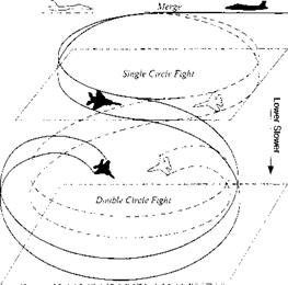
11.1.3.2 Circle fights. In CIC engagements the opponents are maneuvering at high load factors almost continuously. Historically, the most common form has been a hard lateral turn in a steeply banked attitude. Although this maneuver presumes a body-fixed, forward-firing gun, the same tactics has been used in analyses of short-range missile engagements. Viewed from above, the flight paths of the opposing aircraft resemble a series of circles, leading to the terminology of circle fight. Viewed from the side, each successive circle is lower than the previous one, owing to the tendency of aircraft to lose altitude when in a steep bank. Overall, the flight paths of all of the participants in a CIC engagement are descending spirals, as illustrated in Fig. 11.5.
Two stylized types, the single-circle and double-circle fights, are important in CIC analysis. In the single-circle model both opponents hold constant altitude during a circular flight path about a common center of rotation. They could be flying toward each other or chasing each other. In the U. S. the chase version of the single-circle fight is known as a Lufbery circle. The head-on, single-circle fight, however, is considered the more important baseline engagement. In the doublecircle fight the opponents fly nonconcentric circular flight paths that are tangent at a single point. Both aircraft turn the same way, either clockwise or counterclockwise.
Before the introduction of air-to-air missiles, these circle fights could easily be assessed. The outcome depended on who could first point the nose of his aircraft at his opponent and keep it pointed there long enough to inflict significant damage with his gun. Aircraft performance and robustness were the deciding factor. These are conflicting design requirements, because an agile aircraft is light, lacking heavy armor and redundant controls. Finding the proper balance shaped the course of fighter development for decades.
Although circle fights were originally used to categorize close-in combat with guns, they have gained new prominence for engagement studies with the new breed
|
Fig. 11.5 CIC engagement as a sequence of circle fights. |
of agile missiles. The format most often seen in the U. S. is the launch acceptable region (LAR) graphic. There are five distinct LAR graphics; those most relevant to circle fights are given the designations LAR-3, LAR-4, and LAR-5, representing the single, double, and Lufbery circles, respectively. The construction of a LAR graphic can best be described by an example.
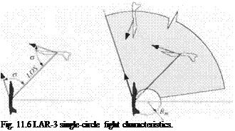
Figure 11.6 illustrates the LAR-3 scenario. The purpose is to simulate a head – on, single-circle fight, at coaltitude and equal speeds. Its prelude begins at great distance, with both aircraft racing straight for each other and trying to fire off their first shot. If both survive the encounter, they merge and begin turning with facing cockpits, setting up the head-on circle.
The geometry of a single-circle fight can be expressed as the relationship between the velocity vectors of the shooter and the target, as shown in the left panel of Fig. 11.6. The slew angle a is the angular displacement of the LOS to the shooter velocity vector at launch. If the target velocity vector makes the same angle to the LOS, the result will describe a single-circle fight.
The LAR-3 envelope follows the format illustrated in the right panel of Fig. 11.6. The shooter aircraft is fixed at the center. The slew angle a is swept incrementally from zero to the largest off-boresight capability of the missile seeker. At each value of (7, the launch range to the target is varied incrementally to identify those initial range conditions that result in hits. The shaded area shown in Fig. 11.6 is the area of successful launch conditions relative to the shooter and is called the launch acceptable region.
Two features of the LAR-3 graphic are noteworthy. First, the full capability of the missile is not normally shown. Because the LAR-3 scenario depicts CIC performance, the envelope is truncated at approximately 6 km. The full performance envelope of a missile could extend to greater distances, but is of little interest.
 |
A second feature of the LAR-3 graphic is the inner exclusion circle defined by the turning radius of the shooter. Launch ranges within that circle result in a crossover between the flight paths of the shooter and target, and both opponents must turn through at least 180 deg before a true single circle can be established. The situation is physically realistic, but does not fit the “circle choreography” selected for LAR-3.
We will use the LAR-3 engagement to study the fidelity issues associated with CIC. Although there are several other types of engagements—the twin circle fights and the British combat circle diagrams, the LAR-3 is representative of the stressing engagements of typical CIC encounters.


